Modbus message area – Yaskawa VS-616G5 Profibus-DP Control Card SI-P User Manual
Page 13
VS-616G5 Option Instruction Manual: Profibus-DP Control Card SI-P
Page 13
MODBUS Message Area
This area is used to transfer MODBUS messages to the inverter. The Profibus-DP master places the
MODBUS command in the output area. The response generated by the inverter is placed in the input area.
The messages can contain 1 - 4 words of data. Since this procedure may take several Profibus
communication cycles, a handshaking protocol is required. The protocol indicates when new commands
and responses are available in the input and output area. Please refer to Yaskawa technical document
PI#95029 entitled “MODBUS Communication for the VS-616G5 inverter” for details and parameter
register addresses.
MODBUS command message structure
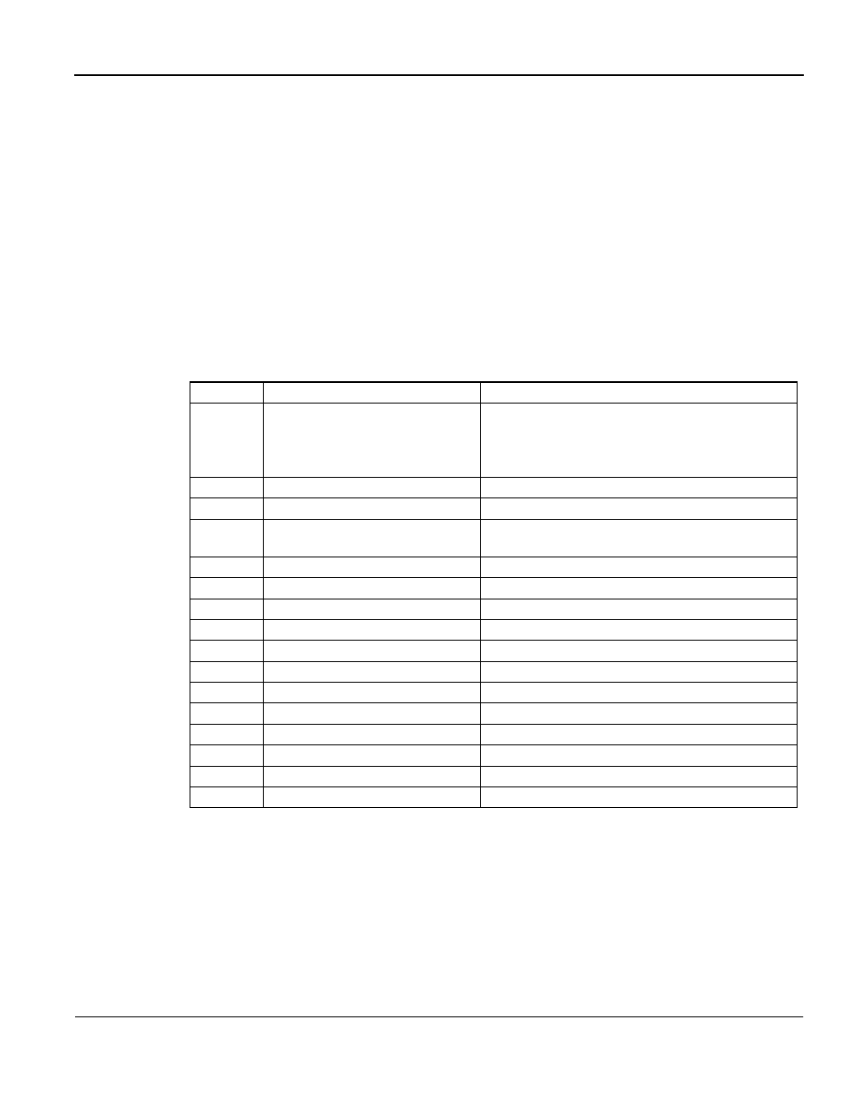
The MODBUS command message is built up as shown in Table 10.
Table 10: MODBUS Command Message Structure (PDP Master
⇒
G5 SI-P)
Byte
Name
Function
16
MODBUS Function Code
MODBUS command code.
03H: Read command
10H: Write
command
Other: Not supported
17
MODBUS Starting address HI
Inverter start address reference, HI byte
18
MODBUS Starting address LOW
Inverter start address reference, LOW byte
19
MODBUS Data Length
Write: No of valid bytes in the data area
Read: No. of requested bytes for read operation.
20
MODBUS Data 1
HI byte for Data word 1. Write operation
21
MODBUS Data 1
LOW byte for Data word 1. Write operation
22
MODBUS Data 2
HI byte for Data word 2. Write operation
23
MODBUS Data 2
LOW byte for Data word 2. Write operation
24
MODBUS Data 3
HI byte for Data word 3. Write operation
25
MODBUS Data 3
LOW byte for Data word 3. Write operation
26
MODBUS Data 4
HI byte for Data word 4. Write operation
27
MODBUS Data 4
LOW byte for Data word 4. Write operation
28
Not used
Reserved for future use
29
Not used
Reserved for future use
30
Not used
Reserved for future use
31
Handshake register
See Handshaking Register section