Yaskawa CM092 User Manual
Page 2
Yaskawa Electric America, Inc. –
www.yaskawa.com
IG.G5HHP.26 Page 2 of 13
Date: 10/12/09 Rev: 09-10
Diagnostic LED Test Sequence
A power-up test is performed each time the drive is powered-up after the initial
boot-up sequence. The initial boot-up sequence may take several seconds.
Seq
MS/RUN
NS/CON
Time
1 GREEN
OFF
250ms
2 RED
OFF
250ms
3 GREEN
OFF
250ms
4 GREEN
GREEN
250ms
5 GREEN
RED
250ms
6 GREEN
OFF
When this sequence is complete, the LEDs will assume normal conditions.
The CM092 EtherNet/IP Option is successfully initialized after the LEDs have
completed the above sequence.
The CM092 EtherNet/IP Option LED status after the power-up sequence is
described in the table below. Please wait for at least five seconds for the loading
process to complete before verifying the status of the LEDs.
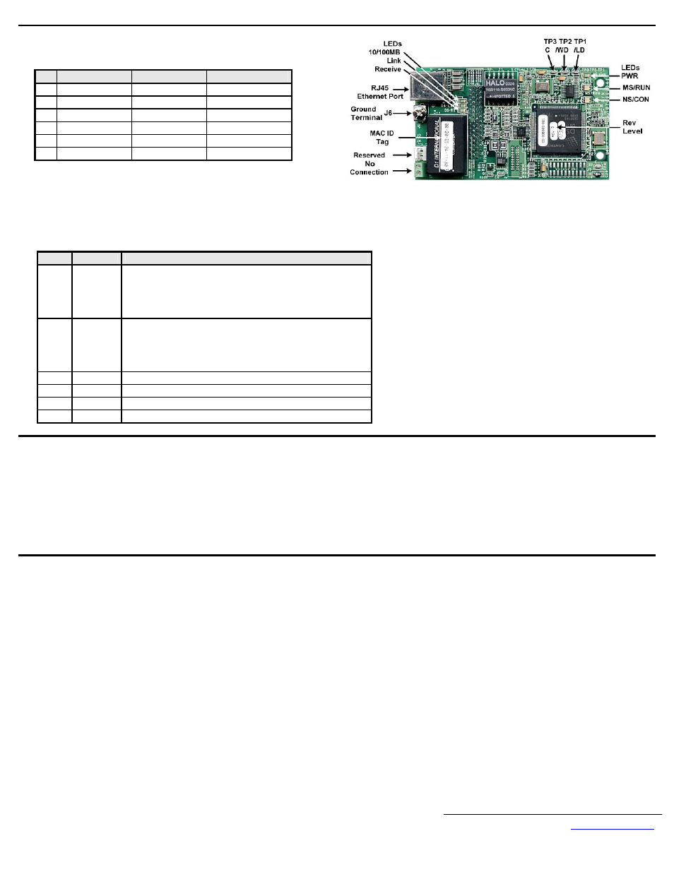
LED
Label
Description
D1 MS/RUN
GREEN – Card Functioning Normally
GREEN BLINK – Standby/Initializing (500ms cycle)
RED BLINK – Minor Fault (500ms cycle)
RED – Major Fault
GREEN/RED BLINK – Module Test (500ms cycle)
D2 NS/CON
GREEN – Connected
GREEN BLINK – Waiting for Connections (500ms cycle)
RED BLINK – Connection Timeout (500ms cycle)
RED – Duplicate IP Address
GREEN/RED BLINK – Network Test (500ms cycle)
D3
10/100
GREEN – 100Mbs Connection Speed
D4 LINK
GREEN – Link Established
D5
Rx
GREEN – Message Being Received
D8 PWR
GREEN - Appropriate Power Supplied to Card
Connect to the CM092 EtherNet/IP Option.
Note: Due to the presence of high voltage in the area of the network connection, insulating the CAT-5 Ethernet cable connection is required.
Prior to connecting the network cable, slide the supplied insulated tubing (4”x1”) over the end of the supplied RJ-45 M-F cable.
Direct connection: To connect directly to the CM092 EtherNet/IP Option, plug one end of a CAT-5 Ethernet crossover cable into the RJ-45 socket on the RJ-45
M-F cable. Connect the other end to the RJ-45 Ethernet socket on the configuration device, typically a controller, laptop or other PC.
Connection through hub or switch: To connect through a switch, hub or router, connect the RJ-45 socket on the RJ-45 M-F cable to a switch, hub or router using
a standard CAT-5 patch cable.
After the network connection is made, slide the insulated tubing (4”x1”) over the connection and secure it in place using the supplied cable ties.
Configure the PC Network Connection.
Select an existing connection or create a new network connection for communication with the CM092 EtherNet/IP Option.
Select Start
→ Settings → Network Connections from the task bar in the Windows OS.
Select the network connection to be used.
Right click on the network connection and select Properties from the menu.
Select Internet Protocol (TCP/IP) from the components displayed.
Note: If a TCP/IP selection is not available, it may be installed by selecting Install. Administrator access to the PC and the OS operating system installation CD-ROM may
also be required.
Select Properties.
Note: If the network connection already has an IP address assigned, ignore the following instructions.
Select the Use the following IP address radio button.
Enter the IP address as 192.168.1.19 and the Subnet mask as 255.255.255.0. Check the system network schematic or with your network administrator to ensure
that the IP address does not already exist on the network.
Once the IP address and Subnet mask are entered, select OK.
Note: It may be necessary to reboot the PC in order for the changes to take affect.