Spindle orientation, Example applications, Required components – Yaskawa G5 Spindle Orientation User Manual
Page 3
Spindle Orientation
Date: 07/01/04, Rev: 04-07
Page 3 of 14
TM.G5SW.021
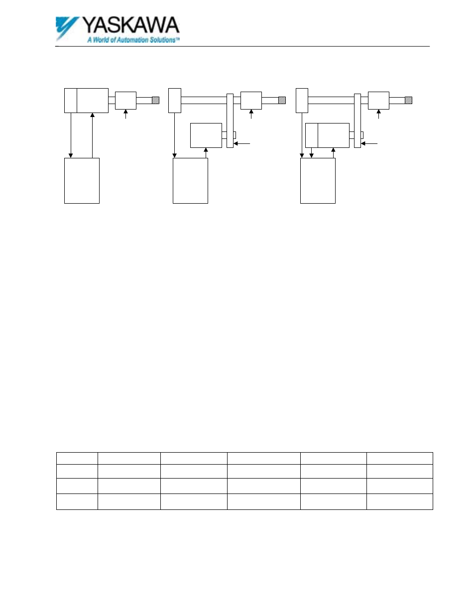
Example Applications
These examples show typical applications. In these examples the encoder Z or marker pulse is used to indicate the zero
or marker position. An external switch may be used as the marker pulse to indicate this position.
Example 1
This is a direct drive system where the encoder, motor and spindle shafts are directly coupled. This system can use the
motor’s encoder for positioning and closed loop vector control of the motor to provide the best performance.
Example 2
This is an indirect drive system where the motor and the spindle shaft are connected through a drive train. The motor
and spindle speeds must have a constant ratio between them. The ratio must be entered into the drive using the provided
ratio parameters. The position encoder is coupled to the spindle shaft. Since there is no motor encoder the drive must be
set to open loop vector control. This configuration will not provide the performance of a closed loop system.
Example 3
This is an indirect drive system where the motor and the spindle shaft are connected through a drive train. The motor
and spindle speeds must have a constant ratio between them. The ratio must be entered into the drive using the provided
ratio parameters. The position encoder is coupled to the spindle shaft. The motor encoder allows for closed loop vector
control. This method will provide the best indirect positioning performance.
Required Components
The application will dictate the required configuration. The configuration will dictate the components needed. The
following table can be used to determine the components needed based on the configurations from the example.
Example
Yaskawa Drive
Software
PG option card
Position Encoder
Motor Encoder
1
G5 / GPD515
VSG11474X
PG-X2
512 to 2048 PPR
Not Required
2
G5 / GPD515
VSG11474X
PG-X2
512 to 2048 PPR
Not Required
3
G5 / GPD515
VSG11474X
PG-W2
512 to 2048 PPR
512 to 2048 PPR
All encoders must be quadrature encoders. The position encoder must have a Z pulse or an external switch must be used
to locate the marker position. DO NOT USE PARAMETER F1-05 TO CHANGE ENCODER PHASING WITH
THIS SOFTWARE. PLEASE SWAP ENCODER SIGNALS A+ AND A- INSTEAD.
Yaskawa
Drive with
PG-X2
Option Card
Motor
E
n
code
r
Tool
Chuck
Tool
Drivetrain
E
n
code
r
Motor
Tool
Chuck
Tool
Spindle Shaft
Drivetrain
E
n
code
r
Motor
Tool
Chuck
Tool
Spindle Shaft
E
n
code
r
(Gear Ratio)
(Gear Ratio)
Example 1
Example 2
Example 3
Yaskawa
Drive with
PG-X2
Option Card
Yaskawa
Drive with
PG-W2
Option Card
Positioned Device
Positioned Device
Positioned Device