Electronic lineshaft with registration, 0 wiring, 1 encoder wiring examples – Yaskawa G5 Electronic Line Shaft User Manual
Page 2
Electronic Lineshaft with Registration
Date: 07/01/04, Rev: 04-07
Sheet 2 of 14
TM.G5SW.047
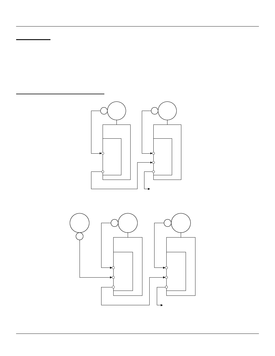
1.0 Wiring
Wire the incoming power, motor, accessories and control wiring as specified in the GPD515/G5 Technical Manual
TM4515. The master encoder (or pulse reference source) should be wired to terminals 10 through 16 according to the
PG-W2 instruction sheet. The registration sensor, if used, must be wired to terminal 7& 8 of the PG-W2 card. Do not
use parameter F1-05 to change encoder phasing in this software. Please swap encoder signals A+ and A-
instead.
Note: The +12V supply on the PG-W2 card is capable of only 200mA, be sure not to overload it.
1.1 Encoder Wiring Examples
GPD 515
PG-X2
TRM 4-7
To additional follower
drives (pulse rate of
master)
Master
Motor
PG
TRM 1-4
GPD 515
PG-W2
TRM 3-6
TRM 10-13
Follower
Motor 1
PG
TRM 17-20
TA1
TA2
Example of a Multiple Follower System with a VFD Driven Master
GPD 515
PG-W2
TRM 3-6
TRM 10-13
PG
To additional follower
drives (pulse rate of
master)
Master
Motor
Follower
Motor 1
PG
TRM 17-20
GPD 515
PG-W2
TRM 3-6
TRM 10-13
Follower
Motor 2
PG
TRM 17-20
Example of a Multiple Follower System (non-VFD Driven Master)