Figure 7, Phase/12-pulse rectification – Yaskawa A1000 6-Phase/12-Pulse Input User Manual
Page 19
n
6-Phase/12-Pulse Input 400 V Class Models 4T0165o to 4T0675o
Gate
Board
Control
Board
Operator
24 V
Power
Supply
+3
R/L1
S/L2
T/L3
R1/L11
S1/L21
T1/L31
ー
U/T1
V/T2
W/T3
Relay
Current
Sensor
+
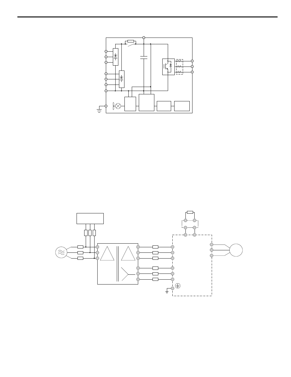
Figure 7 Connecting Main Circuit Terminals
n
6-Phase/12-Pulse Rectification
Installing a Transformer
Install a 6-Phase/12-Pulse isolation transformer with output windings phase-shifted by 30 electrical degrees or install a Hybrid
6-Phase topology on the power supply.
Installing a 3-Phase Line Monitor
Yaskawa requires installation of a 3-Phase line monitor to protect the drive in the event of an input line phase loss.
The 3-Phase line monitor must be installed on the primary circuit of the 6-Phase/12-Pulse transformer and connected to the
drive to remove the Run command when a phase loss condition occurs.
The drive power circuit may be damaged during a phase-loss condition if a 3-Phase line monitor is not properly installed.
Contact a Yaskawa representative for help selecting the optimum 3-Phase line monitor and fuses.
Connection Diagram
U/T1
V/T2
W/T3
R/L1
S/L2
T/L3
R1/L11
S1/L21
T1/L31
CDBR dynamic braking unit
(option)
<2>
Dynamic braking resistor
(option)
<1>
Motor
+3
-
Main Circuit
Power Supply
6-Phase/12-Pulse
Isolation Transformer
3-Phase Line Monitor
Fuse
BCP
Fuse
<3>
<4>
Figure 8 Main Circuit Terminal Connections
<1> A dynamic braking resistor can be connected to the B1 and B2 terminals on models 4T0058o and 4T0072o.
<2> A CDBR dynamic braking unit cannot be connected to models 4T0058o or 4T0072o.
<3> Refer to local codes for proper branch circuit protection (BCP) on the primary side of the 6-Phase/12-Pulse transformer.
<4> Fuse selection for the secondary side is of the 6-Phase/12-Pulse transformer is shown in
3 Electrical Installation
YASKAWA TOEP YAIA1U 02A YASKAWA AC Drive – A1000 6-Phase/12-Pulse Input Installation Manual
19