Efer to, Figure 7, 5 installation procedure – Yaskawa PG-E3 Motor Encoder Feedback User Manual
Page 16
5 Installation Procedure
YASKAWA ELECTRIC TOBP C730600 52C 1000-Series Option PG-E3 Installation Manual
15
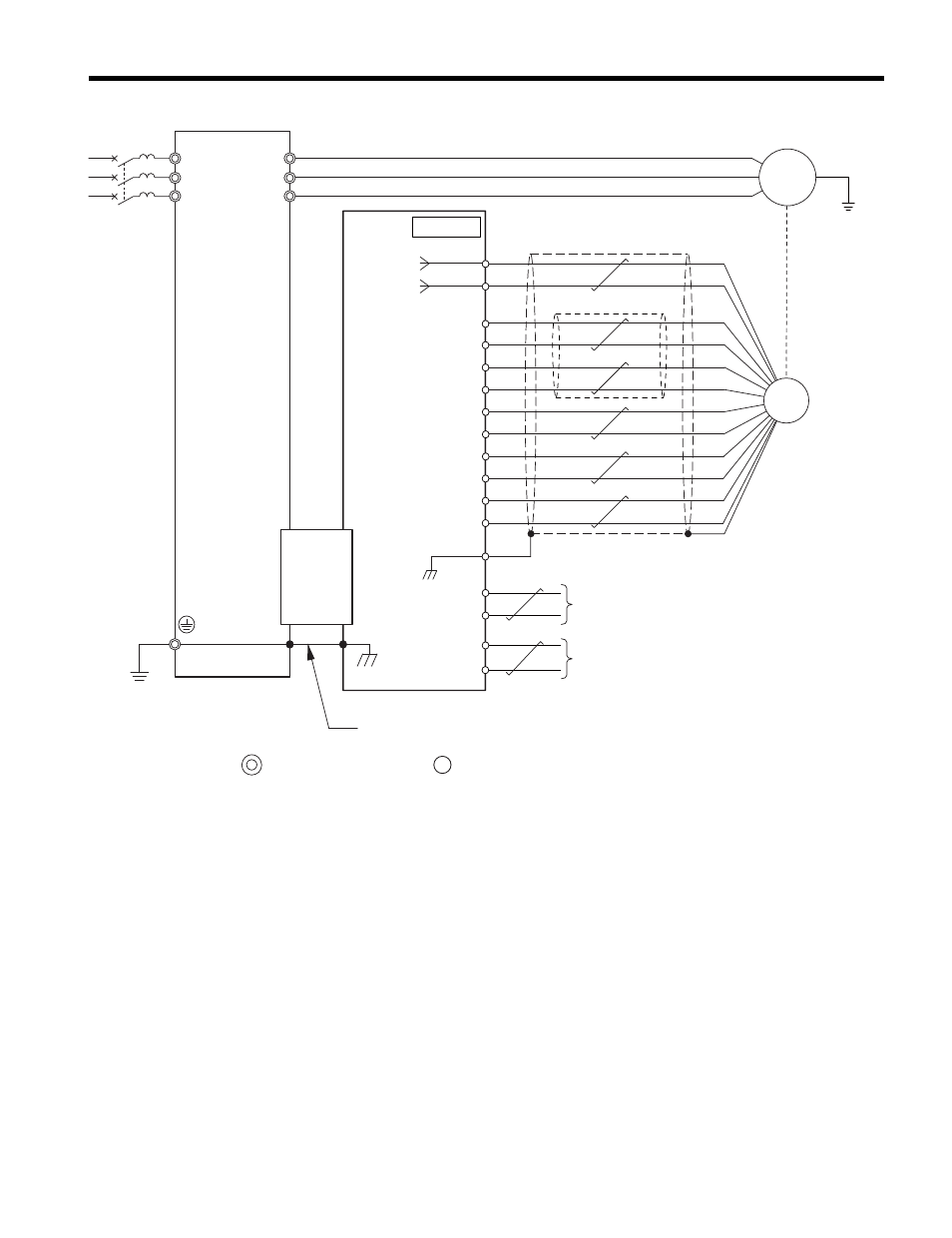
Figure 7
Figure 7 PG-E3 Option and PG Encoder Connection Diagram
<1> Properly connect the shield in cable to terminal IG on the option Terminal Block
TB2 or remove the ground connection on both ends.
<2> Ground the shield on the PG encoder side and the drive side. If noise problems
arise in the PG encoder signal, remove the shield ground from one end of the
signal line or remove the shield ground connection on both ends.
Figure 8
a
–
0 V
5 V
IP
IG
A+
B+
C+
C
–
D+
R+
FE
D
–
R
–
B
–
A
–
M
CN5-C
YASKAWA
Drive
PG-E3
Option
U/T1
V/T1
W/T1
R/L1
S/L2
T/L3
FE
TB1,TB2
a+
b+
b
–
Cable
(by HEIDENHAIN)
Shield in cable
<1>
Encoder
A pulse monitor signal
B pulse monitor signal
main circuit terminal control circuit terminal
<2>
Ground wire
E3