1 setting the mechanical stops of joints #1 and #2 – Epson G3 Series User Manual
Page 62
Setup & Operation 5. Motion Range
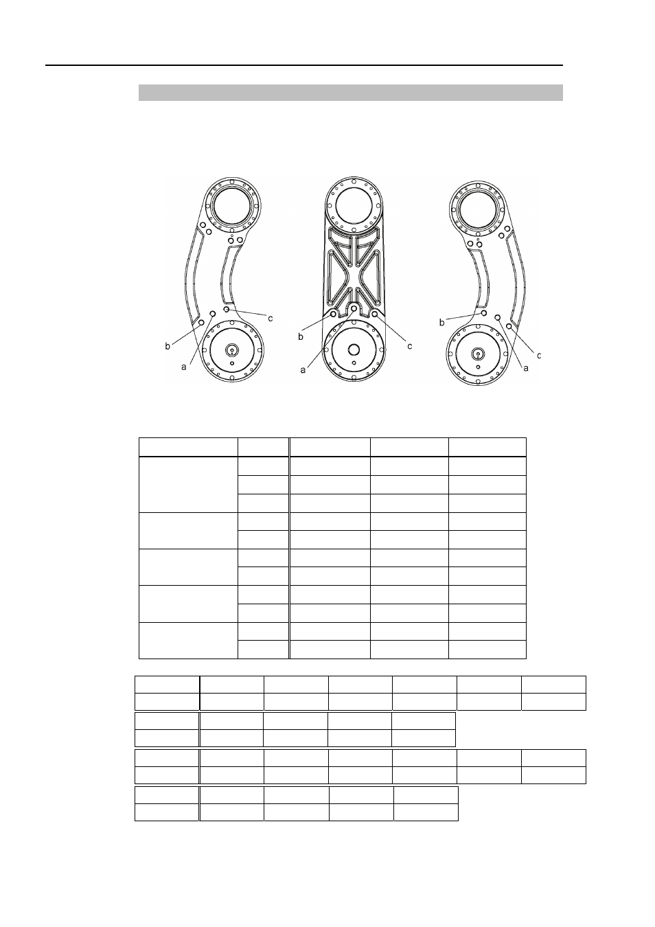
5.2.1 Setting the Mechanical Stops of Joints #1 and #2
Both Joints #1 and #2 have threaded holes in the positions corresponding to the angle for
the mechanical stop settings. Install the bolts in the holes corresponding to the angle that
you want to set.
R L
Joint #1 Mechanical Stops
Views from the bottom of Arm #1
Model Arm a
b
c
250
±
140
°
-110°
+110
°
300
±
140
°
-110°
+110
°
G3-**1S/C
350
±
140
°
-110°
+110
°
300
-125° ~ +150°
-105°
+130
°
G3-**1S/C-R
350
-110° ~ +165°
-90°
+145
°
300
-150° ~ +125°
-130°
+105
°
G3-**1S/C-L
350
-165° ~ +110°
-145°
+
90
°
300
±
115
°
-85°
+85
°
G3-**1SM/CM
350
±
120
°
-90°
+90
°
300
-130° ~ +105°
-100°
+75
°
G3-**1SM/CM-R
350
-105° ~ +130°
-75°
+100
°
Setting Angle
+75°
+85
° +90° +100° +105° +110°
Pulse Value
2184533
2475805 2621440 2912711 3058347 3203982
Setting Angle
+140
°
+145°
+150
° +165°
Pulse Value
4077796
4223431
4369067 4805973
Setting Angle
-75°
-85°
-90°
-100°
-105°
-110°
Pulse Value
-2184533
-2475805
-2621440
-2912711
-3058347
-3203982
Setting Angle
-140°
-145°
-150°
+165
°
Pulse Value
-4077796
-4223431
-4369067
-4805973
(°: degree)
52
G3 Rev.1