3 connecting the ripple control receiver – SMA POWER CONTROL MODULE User Manual
Page 15
SMA Solar Technology AG
5 Electrical Connection
Installation Manual
PWCBRD-10-IA-en-14
15
5. Fasten the module using the screw M4x10 and a
Torx screwdriver (T 20) (torque: 1.5 Nm).
5.3 Connecting the Ripple Control Receiver
Additionally required material (not included in scope of delivery):
☐ Ripple control receiver with at least three outputs
☐ One connection cable
Cable requirements:
☐ Cable cross-section: 5 mm to 13 mm
☐ Conductor cross-section: 0.5 mm² to 1.5 mm²
☐ Maximum cable length: 100 m
☐ Cables to be laid outdoors must be UV-resistant or routed in a UV-resistant cable channel.
☐ Required number of insulated wires for connecting the ripple control receiver: five insulated
wires
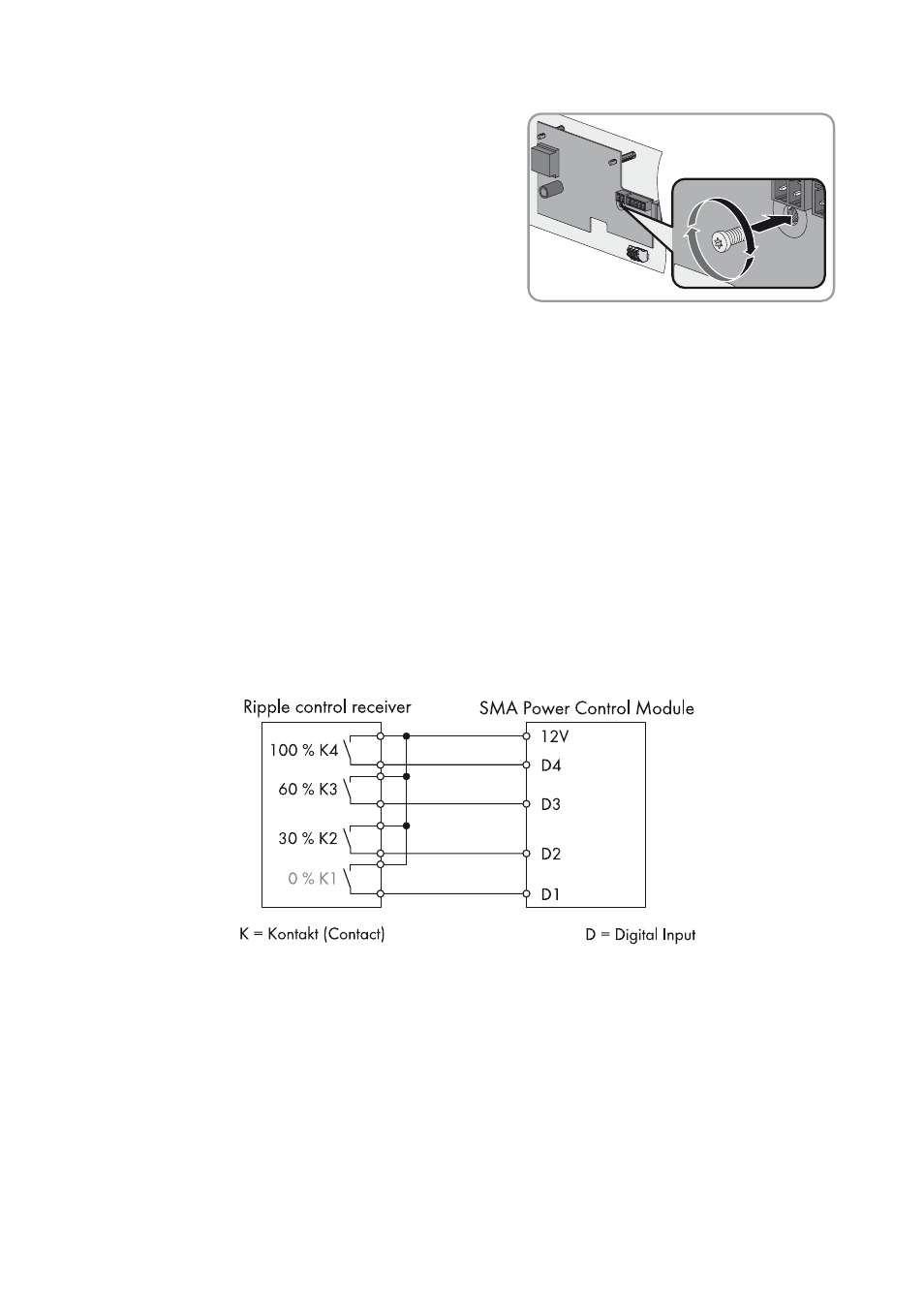
Figure 5: Wiring overview for a ripple control receiver with four relays (example)
- SUNNY PORTAL (75 pages)
- SB 2.5-1VL-40 (60 pages)
- SB 2.5-1VL-40 Service Manual (36 pages)
- SB 240 (78 pages)
- FLX Pro 17 (12 pages)
- FLX Series GSM Option Kit (48 pages)
- FLX Series Sensor Interface Option (51 pages)
- FLX Series PLA Option (62 pages)
- FLX Series (248 pages)
- 25000TL (52 pages)
- 25000TL Installation (40 pages)
- 25000TL Service Manual (46 pages)
- CBL-DC-CMB8-10 (24 pages)
- 25000TL Quick Installation Guide (36 pages)
- STP 60-10 Replacing a Defective Fan (12 pages)
- STP 60-10 Replacing Defective Surge Arresters (12 pages)
- Webconnect Systems in SUNNY PORTAL (69 pages)
- STP 12000TL (68 pages)
- STP 60-US-10 Installation (232 pages)
- 485 Data Module Type B (24 pages)
- STP 12000TL Quick Installation Guide (28 pages)
- 1000-US (52 pages)
- STP 24000TL-US (78 pages)
- STP 17000TL (60 pages)
- STP 20000TL (2 pages)
- SB 6000TL Service Manual (46 pages)
- MULTIFUNCTION RELAY (32 pages)
- SB 5000TL (60 pages)
- SB 5000TL Quick Installation Guide (32 pages)
- FANKIT01-10 (24 pages)
- SB 7700TL-US (28 pages)
- FANKIT02-10 (24 pages)
- SB 7700TL-US Installation (96 pages)
- SUNNY MINI CENTRAL (48 pages)
- DC Disconnect Switch For SB 3800-U (32 pages)
- SB 4000-US (100 pages)
- DB-DC-DISCON (4 pages)
- SB 3800-U (86 pages)
- POWER BALANCER (28 pages)
- SB 8000-US (104 pages)
- SB 11000TL‑US (40 pages)
- SMC 11000TL (24 pages)
- SBCBTL6 (36 pages)
- SB 11000TL‑US Installation (92 pages)
- SMC 11000TL Installation (96 pages)