3 connecting the data cable in the ssmxx-21-bs-jp – SMA SSM8-21-BS User Manual
Page 34
6 Electrical Connection
SMA Solar Technology AG
34
SSMxx-21-IA-BS-JP-en-20
Installation Manual
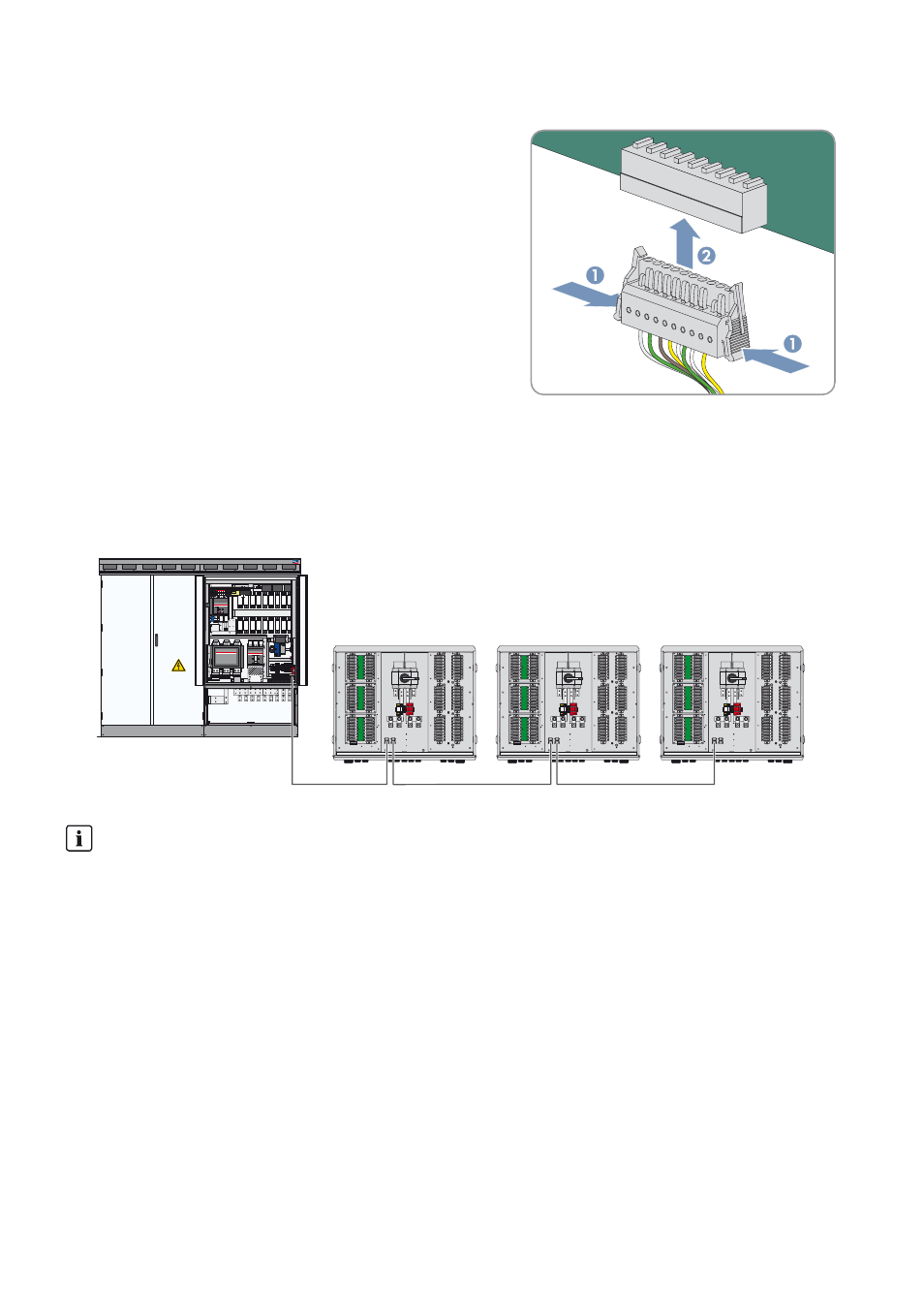
Connecting the Connector to the String-Monitor Unit
• Plug the connector with the connected data cables into the pin
connector of the lowest String-Monitor Unit.
6.7.3 Connecting the Data Cable in the SSMxx-21-BS-JP
The Sunny String-Monitors must be connected to the RS485 communication bus and supplied with voltage.
The RS485 data cables and the voltage supply are connected jointly in one data cable to terminals -X712 and -X713
by means of a connector. This means that two data cables will be connected to each Sunny String-Monitor. Only one
data cable is connected and terminated at the last Sunny String-Monitor.
Figure 15: Connection of Sunny String-Monitors to the RS485 communication bus (example)
Procedure:
To connect the data cables in the Sunny String-Monitor, carry out the following steps in the given sequence. The exact
procedure is described in the following sections.
• Preparing the data cables
• Connecting the data cables to the connectors
• Connecting the connectors in the Sunny String-Monitor
Limited number of String-Monitor Units per Ethernet hub
Since the String-Monitor Unit measurement PCBs are supplied with voltage via the data cables, the number of
connected String-Monitor Units is limited.
• Do not connect more than ten String-Monitor Units per Ethernet hub.
The various types of Sunny String-Monitors are equipped with differing numbers of String-Monitor Units:
• Sunny String-Monitor SSM8-21: 1 String-Monitor Unit
• Sunny String-Monitor SSM16-21: 2 String-Monitor Units
• Sunny String-Monitor SSM24-21: 3 String-Monitor Units