B. cartridge heater, C. thermostat, D. sample capillary – Emerson Process Management 760004-A User Manual
Page 51: 10 thermal block assembly, Model nga 2000 hfid
Instruction Manual
760004-A
February 2002
Rosemount Analytical Inc. A Division of Emerson Process Management
Maintenance and Service 4-13
Model NGA 2000 HFID
b. Cartridge
Heater
1. Remove oven from analyzer module
per Section 4-2a.
2. Remove burner/thermal block from
oven per Section 4-2b.
3. Refer to Figure 4-9. Loosen retaining
set screw, pull out cartridge heater.
4. Install replacement cartridge heater,
snug down set screw.
5. Install burner/thermal block into oven.
6. Install oven into analyzer module.
c. Thermostat
1. Remove oven from analyzer module
per Section 4-2a
2. Remove burner/thermal block from
oven per Section 4-2b.
3. Refer to Figure 4-9. Remove the two
retaining screws, pull thermostat out.
4. Install replacement thermostat, attach
with the two retaining screws.
5. Install burner/thermal block into oven.
6. Install oven into analyzer module.
d. Sample
Capillary
1. Remove oven from analyzer module
per Section 4-2a
2. Remove burner/thermal block from
oven per Section 4-2b.
3. Remove burner from thermal block
per Section 4-4a
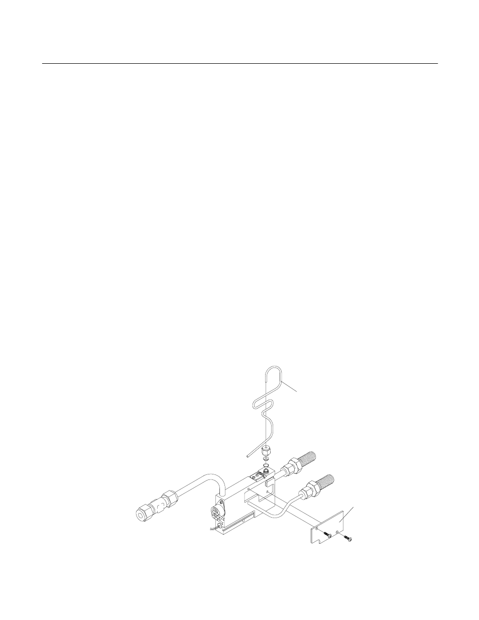
4. Refer to Figure 4-10. Remove the
two screws securing the capillary
cover to thermal block, remove cover.
5. Remove capillary nut, remove capil-
lary.
6. Install replacement capillary.
7. Insert capillary into thermal block.
The capillary may require bending to
fit.
8. Install
cover.
Figure 4-10. Thermal Block Assembly
Capillary
Cover