ShoreLand'r CL2438TB-HYD User Manual
Page 5
5
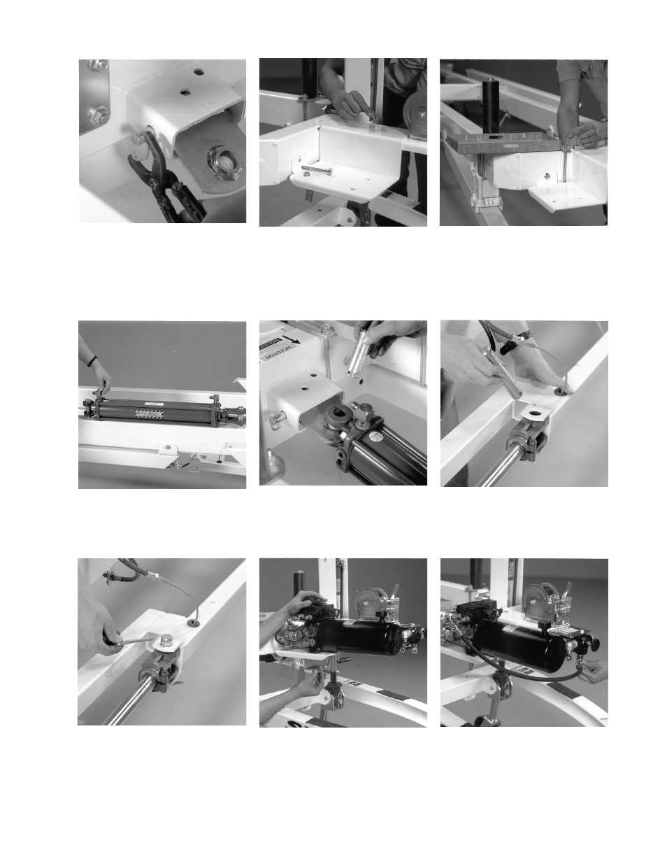
10. Secure the 5/8 X 6-5/8 pin (Ref.#1)
with hog rings (Ref.#10) as shown.
11. Mount the pump mounting bracket
(Ref.#16) to the center lift frame using
one (1) 3/8 X 3-3/4 carriage bolt
(Ref.#68) through the side frame and
one (1) 3/8 X 1 carriage bolt
(Ref.#66) down through the winch
mounting plate as shown. Secure with
3/8 flange lock nuts (Ref.#8).
12. Mount the battery mounting plate
(Ref.#51) to the frame as shown using
two (2) 3/8 X 3-1/16 X 5-7/8 square
u-bolts (Ref.#75) and secure with four
(4) 3/8 flange lock nuts (Ref.#8).
13. Insert the 90° straight elbows
(Ref.#98) into the larger lift cylinder
(Ref.#87).
14. Secure the lift cylinder (Ref.#87) to the
pivot plate (Ref.#47) using a 1
cylinder pin provided as shown.
15. Extend the cylinder until it will line up
with the hole on the lift tube weldment
(Ref.#54). Secure the other end of the
lift cylinder link (Ref.#57) using a 1
cylinder pin provided as shown.
16. Secure the cylinder pins with the
cylinder locking pins as shown.
17. Mount the hydraulic pump (Ref.#13) to
the pump mounting plate (Ref.#16)
using two (2) 3/8 X 3/4 hex bolt
(Ref.#101) and two (2) 3/8 lock
washers (Ref.#24).
18. Secure the hydraulic hoses. Refer to
page 7 in this manual for assistance.