Diagram c – ShoreLand'r SLB150TAL User Manual
Page 6
Midwest Industries, Inc.
Ida Grove, IA 51445
800.859.3028
www.shorelandr.com
0004000
Page 6
09/15/2008
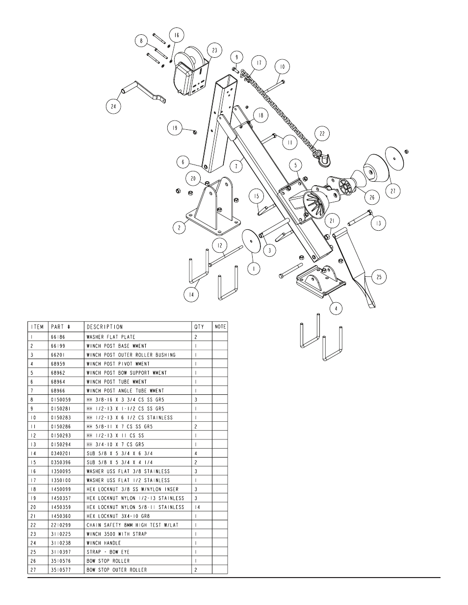
Winch Assembly:
Refer to page ? for winch parts diagram.
The winch post assembly comes factory assembled and ready to
mount on the tongue. Position the winch assembly on the tongue
in a location that would best fit your watercraft. Using two (2) 5/8” X
5-3/4” X 6-3/4” stainless steel square u-bolts, secure the winch as-
sembly to the tongue. Tighten with four (4) 5/8” stainless steel lock
nuts so that the winch assembly will not slide on tongue. Set the
other mounting plate in position and secure it using two (2) 5/8” X
5-3/4” X 6-3/4” stainless steel square u-bolts and four (4) 5/8” stain-
less steel lock nuts. Refer to winch adjustments on page ?.
Jack:
Remove the hardware bag provided by the jack manufacturer and
take out the mounting plates. From hardware bag (66270), take out
four (4) 3/8” X 6” stainless steel hex bolts and four (4) 3/8” stainless
steel lock nuts with nylon inserts, Position the jack on the tongue
in a location that best fits your watercraft. Secure with the stainless
steel hardware. The remaining hardware bag that was removed
from the jack may be discarded.
Diagram C