Diagram b breakaway switch – ShoreLand'r SLB150TAL User Manual
Page 3
Midwest Industries, Inc.
Ida Grove, IA 51445
800.859.3028
www.shorelandr.com
0004000
Page 3
09/15/2008
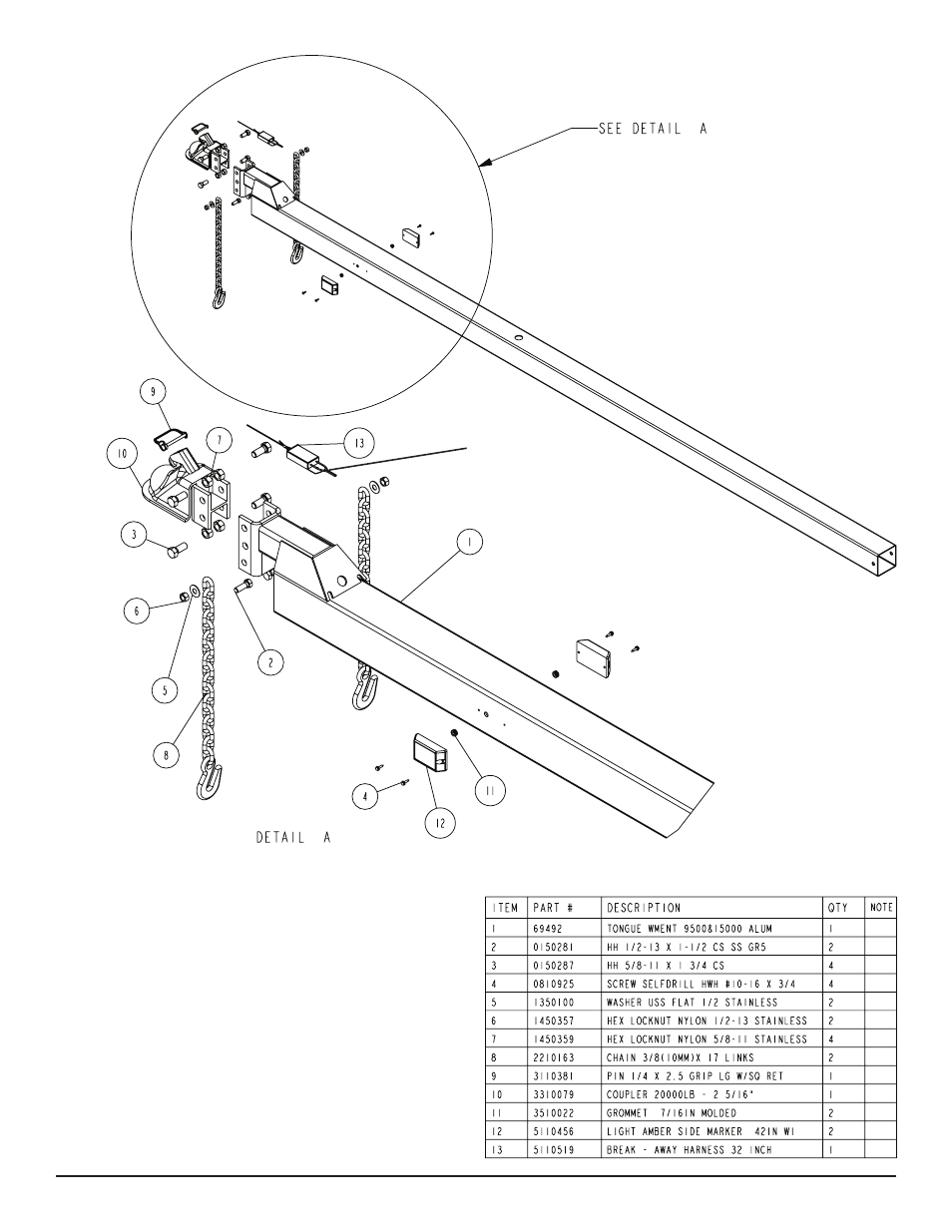
Tongue:
Slide the tongue into the tongue channel weldment on front cross-
member. Secure the tongue with a 5/8” X 7” stainless steel hex bolt,
5/8” stainless steel flat washer and 5/8” stainless steel hex lock nut
with nylon insert.
Secure the tongue to the tongue plate on the frame using two (2)
5/8” X 5-3/4” X 6-1/2” square u-bolts and four (4) 5/8” stainless
steel hex lock nut with nylon inserts.
Coupler / Safety Chain:
Mount the coupler onto the tongue (matching the hole pattern) us-
ing four (4) 5/8” X 1-3/4” stainless steel hex bolts and four (4) 5/8”
stainless steel hex lock nuts with nylon inserts.
Mount the safety chains to the front of the tongue using a 1/2” X
1-1/2” stainless steel hex bolts, followed by a 1/2” stainless steel flat
washer and safety chain. Secure this assembly on the inside of the
tongue using a 1/2” stainless steel hex lock nut with nylon insert.
Repeat the above instructions on the other side of the tongue.
Diagram B
Breakaway Switch