Diagram d – ShoreLand'r SLB150TAL User Manual
Page 4
Midwest Industries, Inc.
Ida Grove, IA 51445
800.859.3028
www.shorelandr.com
0004000
Page 4
09/15/2008
Wiring Instructions
The attaching hardware for the actuator and the battery boxes on
the aluminum trailers is stainless steel. They require that you use
the appropriate size nuts with the nylon inserts.
• Open the box containing all the items required for installing the
electric over hydraulic brake system.
The wire harness for the brake system and lighting is pre-wired with
mating plugs to simplify the connection process. Also the rear por-
tion of the tongue harness has been installed at the factory.
• Place the wire harness supplied in the box into the front of the
tongue so the large round 7 prong plug remains out the front of the
tongue.
• Pull the wire harness into the tongue and route it out the top of the
tongue through the large hole provided.
• Pull all of the wire ends with bullet plugs and mating plugs out
the hole in the top of the tongue including the white wire with the
grounding ring.
• Connect the single bullet ends of the brown, yellow and green
wires of this wire harness to the mating plugs of the factory installed
wire harness for the rear section of the tongue. These wires are
extending out the hole in the top of the tongue and are taped there
during shipping.
• Once attached these wires can be placed down inside the
tongue.
• The white wire with the grounding ring will be attached later
when the battery boxes are fastened to the side frames. This white
grounding wire is used only for a grounding system for the trailer
lights and has nothing to do with the brake system which has its
own grounding system pre-wired in the harness.
• Locate the two wire plugs: brown and yellow, and brown and
green at the rear of the tongue. Mate these plugs with those of
the side frame wire harnesses and plug together making sure they
have a good connection. Place any excess wiring inside the rear
of the tongue.
• See Diagram B. Locate the breakaway switch that is already at-
tached and wired into the main wire harness just installed in the
front of the tongue. Position it so it is approximately 3” behind the
coupler. Mark the mounting hole location. Drill a 13/64” pilot hole
in the tongue. Insert the ¼” self-drilling screw provided and secure
in place.
Battery Box Installation Instructions
Locate the battery boxes. Note that there are two battery boxes and
two batteries. They are both required to power the brake system in
the event of a disconnect from the tow vehicle.
1. Attach the two battery boxes to the front of the side frames mat-
ing the holes in the battery boxes with those pre-drilled in the side
frames. Mount them to the side frames using ¼” x 1” carriage bolts
and ¼” lock nuts. Place the grounding ring attached to the end
of the white ground wire to one of the screws before the nut is
threaded on. Once all bolts are installed, tighten.
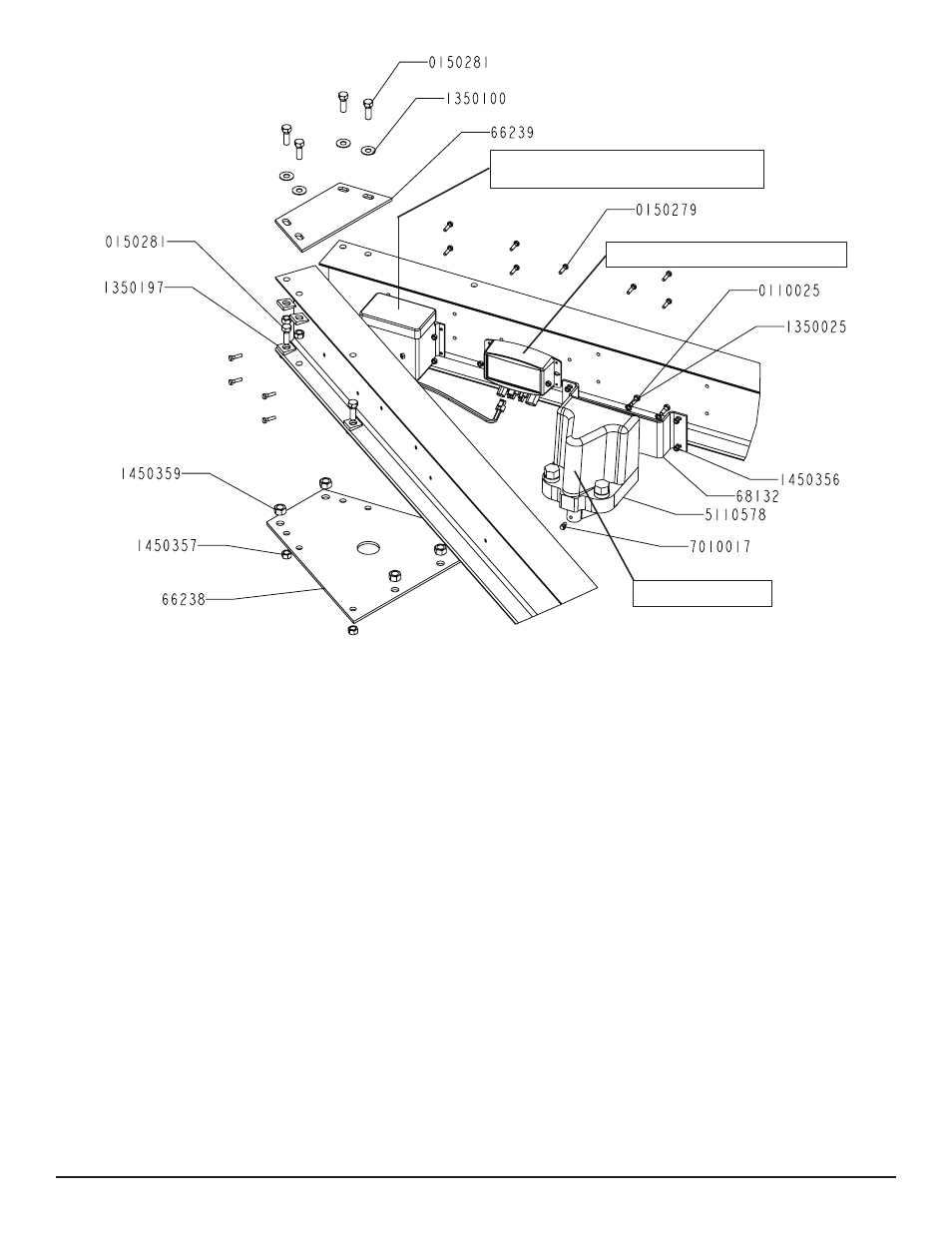
Diagram D
Battery Boxes
(one mouted to each side frame)
SD Control Module
Actuator