Profile3d measurements, 1 oper ation – HEIDENHAIN IK 5000 Addendum User Manual
Page 39
IK 5000 QUADRA-CHEK
39
1
.1 Oper
ation
Profile3D measurements
Profile3D measurements compare probed part surfaces to nominal
part profiles from drawing or part data files. Probed surfaces and
nominal profile surfaces are compared in the Measure Profile3D
window.
The nominal part profile can be imported into the Measure Profile3D
window from a drawing file in .IGS or .STP formats.
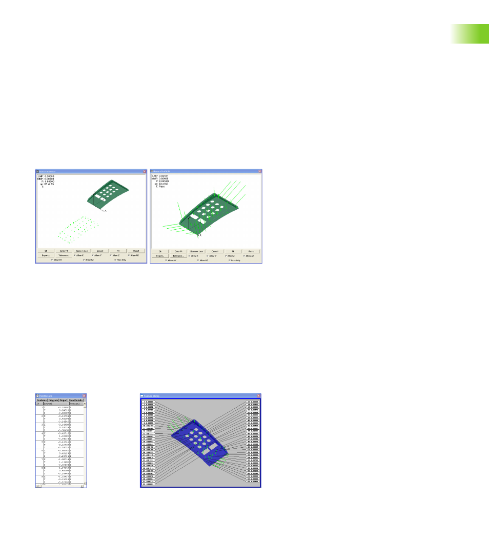
As surfaces are probed, their points are displayed in the Measure
Profile3D window. When the desired surface measurements are
complete, a fit operation is performed. During the fit operation, the
system positions the probed data over the nominal profile and adjusts
the X, Y, Z and rotational orientation of the probed points to achieve
the best fit. Data points are shown as dots and form errors are shown
as whiskers.
Tolerances can be applied to Profile3D measurements as bilateral
limits or as unilateral pass/fail boundaries. Bilateral tolerances can be
distributed equally or unequally on opposite sides of a surface.
The form errors, the number of data points and tolerance pass/fail
results can be displayed in the Measure Profile3D window at the
conclusion of the Fit operation. Upon completion of the Profile3D
measurement, the Profile3D feature is listed in the Features template.
The form error of each surface point is listed in the Points Detail
template and can be visually inspected using the Profile3D Feature
Stamp.
Probed points shown in Measure
Profile3D window
Fit operation performed and form
error whiskers shown
Points Detail template
Profile3D feature stamp