Grass Valley LDK 7500 Technical Manual User Manual
Page 3
03.18.5
Technical Manual LDK 7500 + LDK 5490 Adapter
iii
0 1 2 3 4
5 6 7 8 9
3 9 2 2 4 0 6 8 8 9 9 1
0 0 1 2 1 1 0 7 0 0 0 1
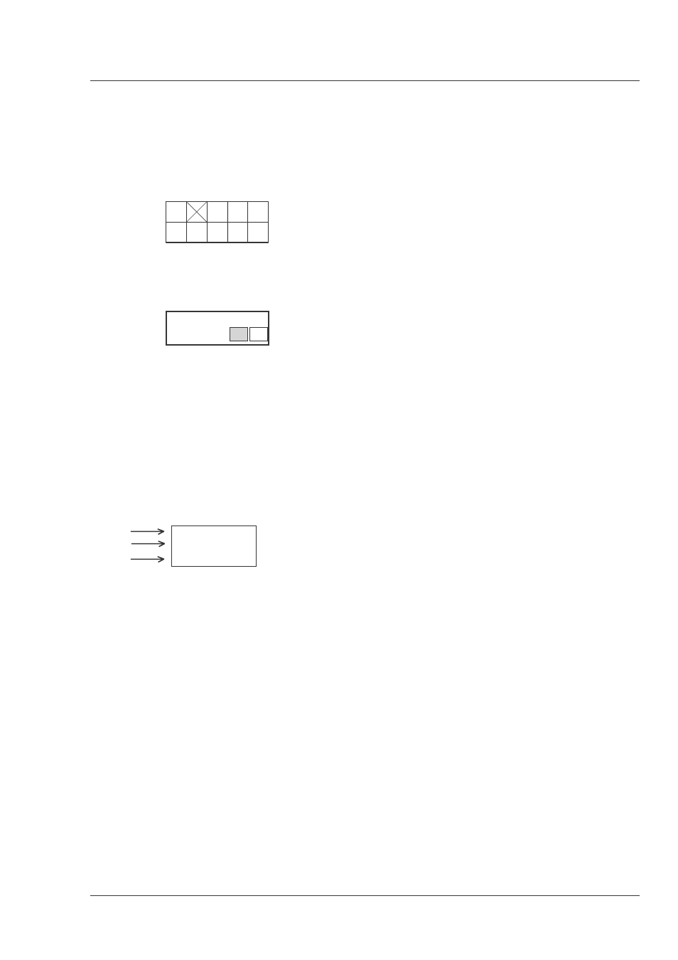
Identification and Status
To indicate the status of a drawing, a box with the
numbers 0 to 9 is shown in the bottom-right of the
drawing. The number that is crossed-out is the status
number of the drawing. For example, in the illustration
below, the status is 1.
A sticker is used on the units themselves to identify
them and to indicate their status. For example, in the
illustration below, the top line is the 12-digit number
that identifies the unit type.
The first four digits of the number on the second line
represent a date code (year, week); the next four digits
represent the serial number for that week.
The number in the grey area indicates the status of the
unit. The last two digits represent the number that will
be given to the next status. However, if these two
digits are contained in a box, then this is the current
status. For example, in the illustration above, the
current status of the unit is 01.
Line 1
3922 407 00000
Line 2
123456AA0101
Line 3
VR/0123456789
Line 1
This is the code number of the printed circuit board
assembly (PCB).
Line 2
This is the serial number of the PCB. The first 6 digits
and the 2 letters are for internal use. The last four digits
reperesent the date of the manufacturing: wwyy.
Example:
123456AA1402 means the PCB is manufactured in
week 14 of the year 2002.
Line 3
This is the status of the PCB.
The digit after the first slash is the status. If there is
no number before the slash, it means that the status
is less than 10, a 1 before the slash means the status
is between 10 and 19, a 2 before the slash means
between 20 and 29 etc.
Example:
VR4567891012 means status 4
VR3/78901234 means status 37.
Example of LDK number:
LDK 4501/01 means 8926 450 10101
LDK 4500/00 means 8926 450 00001
Numbers of printed circuit board assembly
- 3922 406 xxxxx or 3922 407 xxxxx
Number (screened in PCB layout) of printed circuit
board assembly: 3922 411xxxxx (not a spare part).