Completely. b. unscrew the four retaining screws – Grass Valley LDK 7500 Technical Manual User Manual
Page 25
Replacements
Technical Manual LDK 7500 + LDK 5490 Adapter
3-5
B G R
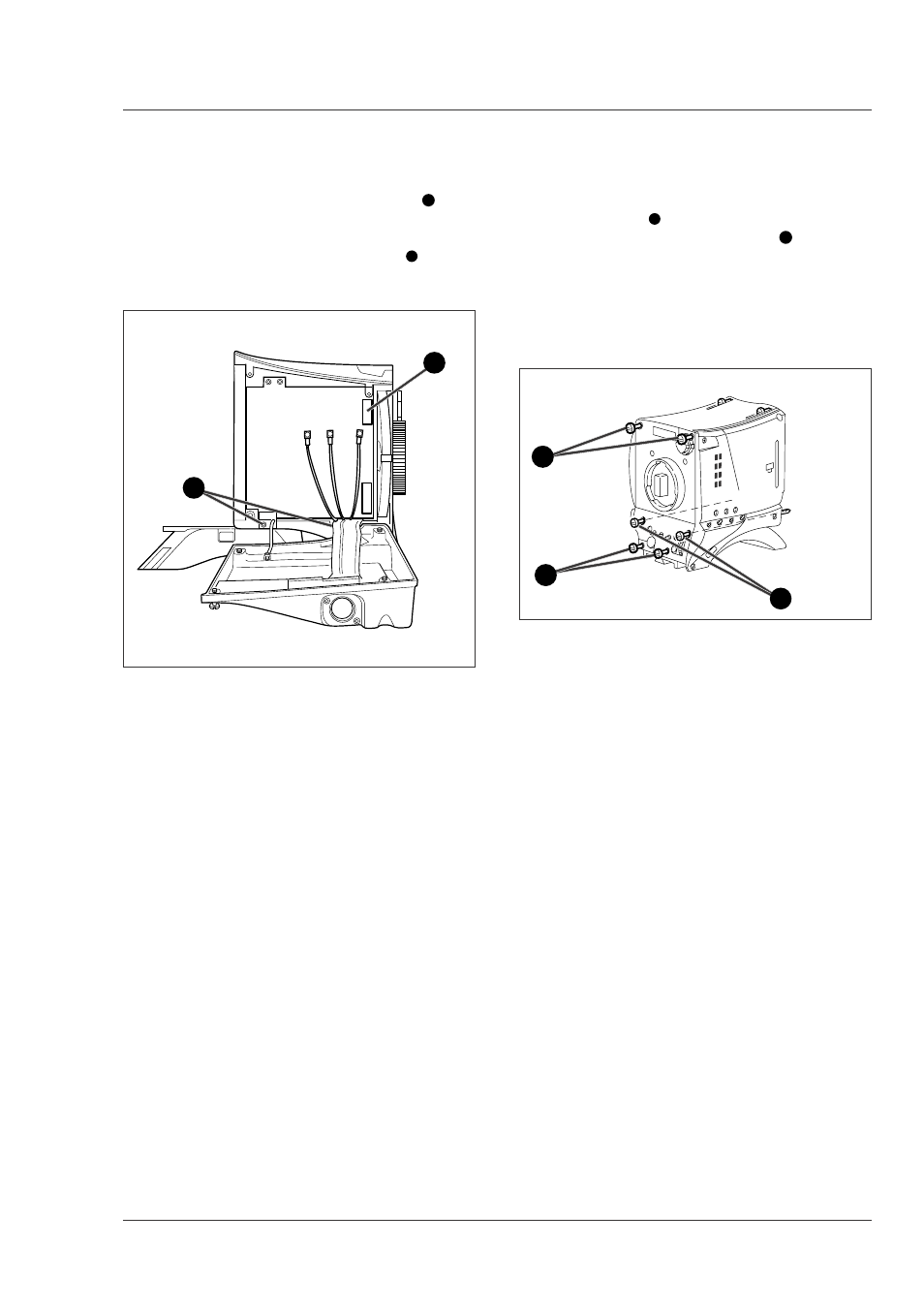
Removing the DVP board
To remove the DVP board proceed as follows:
h. Unscrew the two bottom retaining screws
7
of the
DVP board from the plastic clips and remove the
board.
i. Unscrew and disconnect the connector
8
from the
Front.
Removing the front unit
To remove the front unit proceed as follows:
a. To ease the removal of the front unit remove the
adapter screws
1
completely.
b. Unscrew the four retaining screws
2
of the front
unit.
c. Move the front unit slightly upwards and forward
and disconnect the flat cable that comes from the
front from the connector on the connector board of
the camera.
d. Remove the front unit.
Clear
Clear
A 1
Star 4P
ND1/4
B 2
Star 6P
ND 1/16
C33
Soft focus
ND 1/64
D 4
7
8
1
2
2
This manual is related to the following products: