Introduction, Handgrip, Securing the handgrip to the front of the camera – Grass Valley LDK 7500 Technical Manual User Manual
Page 22
3-2
Technical Manual LDK 7500 + LDK 5490 Adapter
Replacements
Clear
Clear
A 1
Star 4P
ND1/4
B 2
Star 6P
ND 1/1
6
C 3
Soft foc
us
ND 1/6
4
D 4
Introduction
The instructions given in this section are restricted to
those modules which can be replaced at the first line
service level. These modules include:
•
The handgrip
•
The printed circuit boards
•
The front unit
After a printed circuit board has been replaced it is
sometimes necessary to carry out adjustments to
match the new boards to your camera and so maintain
the performance levels. The relevant adjustment
procedures are given in Section 4.
The procedures for removing the modules should be
followed in reverse order when remounting the units.
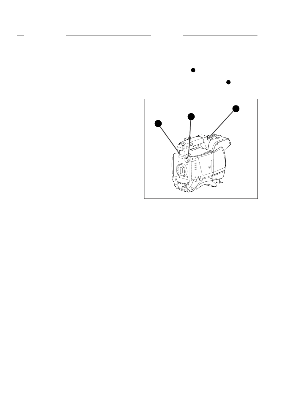
To remove the handgrip proceed as follows:
a. Remove the viewfinder from its support bracket on
the handgrip.
b. Loosen the screw
1
securing the handgrip to the
top of the adapter.
c. Loosen the two socket head screws
2
securing the
handgrip to the front of the camera.
Handgrip
1
2
2