Front unit – Grass Valley LDK 7500 Technical Manual User Manual
Page 24
3-4
Technical Manual LDK 7500 + LDK 5490 Adapter
Replacements
Clear
Clear
A 1
Star 4P
ND1/4
B 2
Star 6P
ND 1/16
C 3
Soft focus
ND 1/64
D 4
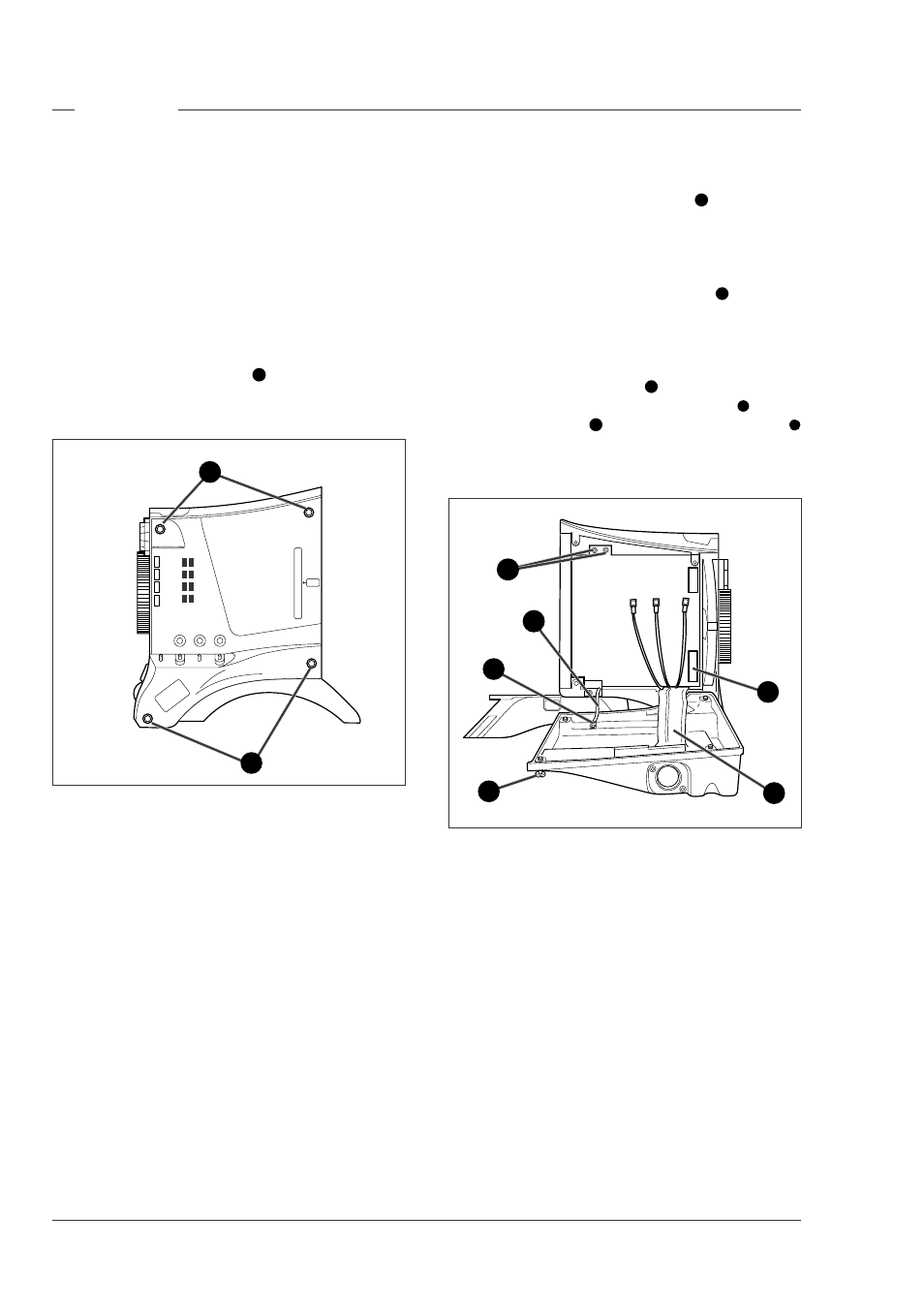
To remove the front unit the following steps have to be
carried out:
•
Loosen the two top screws
•
Open the camera left side cover
•
Open the camera right side cover
•
Remove DVP board
•
Remove the front unit
Front unit
B G R
Opening the right side cover
To remove the right front cover proceed as follows:
a. Unscrew the four retaining screws
1
and swing the
right front cover down.
b. Disconnect the B, R and G coax cables from the
DVP board using the correct tool (part no. 5322 395
10802)
c. Unscrew the two top retaining screws
2
of the DVP
board and swing the board downwards.
d. Reach in behind the board and disconnect the flat
cable from the connector at the bottom of the
board.
e. Disconnect the flat cable
3
that comes from the
cover, from the motherboard connector
4
.
f. Loosen the screw
5
and remove the retaining tie
6
that restrains the cover.
g. Remove the cover.
x4
Opening the left side cover
To open the left side cover proceed as follow:
a. Loosen the four screws
1
at the front of the
camera.
b. Swing down the cover
1
1
1
2
3
4
5
6