Printed circuit boards, And pull down the bottom print ejector – Grass Valley LDK 7500 Technical Manual User Manual
Page 23
Replacements
Technical Manual LDK 7500 + LDK 5490 Adapter
3-3
Clear
Clear
A 1
Star 4P
ND1/4
B 2
Star 6P
ND 1/16
C 3
Soft focus
ND 1/64
D 4
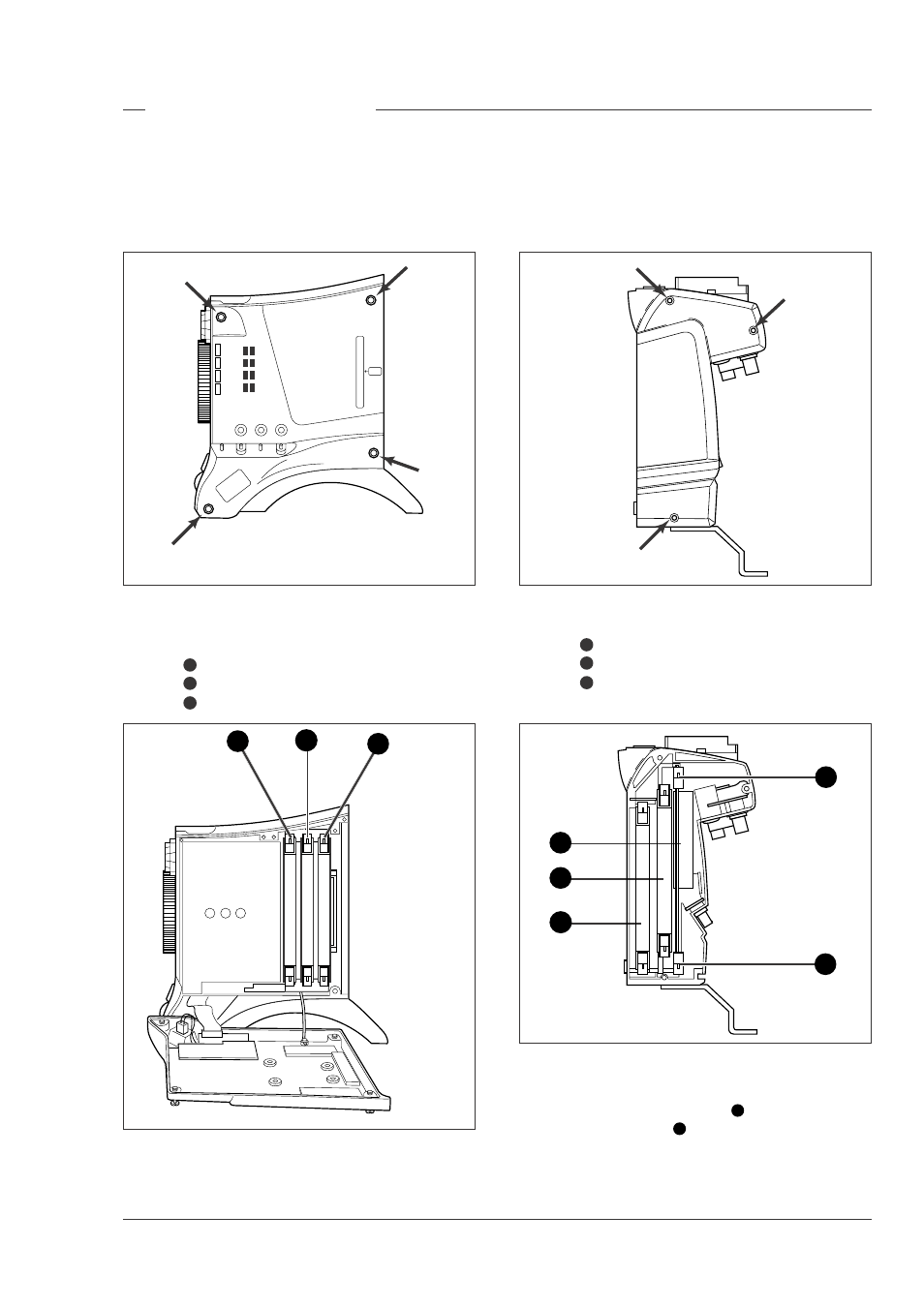
Printed circuit boards
Gaining access to camera head boards
To access the printed circuit boards remove the left
side cover of the camera head as follows:
a. Unscrew the four screws on the left side panel.
b. Swing down the cover.
Location of boards
The boards in the camera head are numbered as
follows:
Sync monitoring board
Data board
Front driver board
1
3
2
4
5
Gaining access to adapter boards
To access the printed circuit boards remove the left
side cover of the adapter as follows:
a. Unscrew the three screws on the left side panel.
b. Remove the cover.
Location of adapter boards
The boards in the adapter are numbered as follows:
Power board
HDSDI output board
Miscellaneous HDSDI board
4
6
5
1
3
2
Removing a board
To remove a printed circuit board proceed as follows:
a. Pull up the top print ejector
7
and pull down the
bottom print ejector
8
to release the printed circuit
board from its connector.
b. Pull horizontally on these ejectors to slide the
board clear of the camera.
6
7
8