Installing the ram, Figure 3. pci board location – Grass Valley PLSDST3 User Manual
Page 12
DST 312/412 Interface Kit Installation
6
DST 312/412 Interface Kit Installation
Installing the RAM
Install the RAM included in this kit if the memory checks described in “Master
and Slave EDR Memory Requirements” beginning on page 2 indicate that there is
less than 64 MB of I/O buffer RAM on the Master or Slave EDR board, and less
than 32 MB of local processor RAM on the Master EDR board.
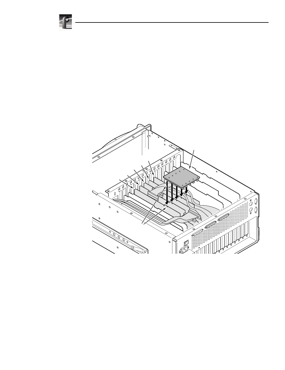
1. Unplug the PCI Interconnect board from the top of the EDR boards. The PCI
Interconnect board is a three- or five-connector board that spans the circuit
boards requiring PCI interconnection. The boards that plug into the PCI
Interconnect board are the MPEG, Fibre Channel, Master EDR, and Slave
EDR boards normally located in slots J8, J9, J10, J11, and J12 and arranged
as shown in Figure 3.
Figure 3. PCI board location
0169-1
Slave EDR Board
MPEG Board
Master EDR Board
Fibre Channel Board
MPEG Board
Alignment Keys
PCI Interconnect
Board