Gpi input structure – Grass Valley Kayenne XL Package Installation v.7.0.2 User Manual
Page 79
Kayenne XL Package — Installation and Service Manual
79
Pin Assignments
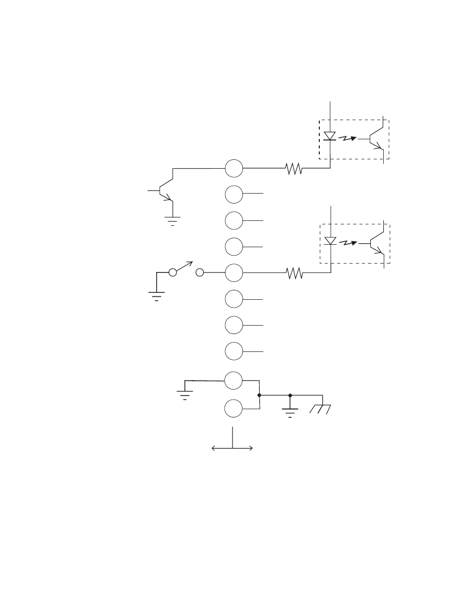
GPI Input Structure
Figure 52. GPI Input Connections (Typical 2 of 8 connections)
Pins 1 and 34 of each of the two (four) connectors are connected to ground.
For applications that span across more than one connector, only one
ground (common) connection is required.
The function of each GPI input is user assignable. The activation of the
function can be programmed to occur on the leading edge or the trailing
edge of the closure, or both edges. The switch must be closed for at least one
field.
50-pin Connector
Pin Numbers
Opto Isolator
(1 of 8)
GPI 1
GPI 5
+ 3.3 V
Open
Collector
18
35
19
36
20
4
1
34
3
2
150 ohm
Opto Isolator
(5 of 8)
Ground and
Chassis
Kayak HD Frame
User Equipment
+ 3.3 V
150 ohm
8448_08
r0
- LDK 5302 (24 pages)
- SFP Optical Converters (18 pages)
- 2000GEN (22 pages)
- 2011RDA (28 pages)
- 2010RDA-16 (28 pages)
- 2000NET v3.2.2 (72 pages)
- 2000NET v3.1 (68 pages)
- 2020DAC D-To-A (30 pages)
- 2000NET v4.0.0 (92 pages)
- 2020ADC A-To-D (32 pages)
- 2030RDA (36 pages)
- 2031RDA-SM (38 pages)
- 2041EDA (20 pages)
- 2040RDA (24 pages)
- 2041RDA (24 pages)
- 2042EDA (26 pages)
- 2090MDC (30 pages)
- 2040RDA-FR (52 pages)
- LDK 4021 (22 pages)
- 3DX-3901 (38 pages)
- LDK 4420 (82 pages)
- LDK 5307 (40 pages)
- Maestro Master Control Installation v.1.5.1 (455 pages)
- Maestro Master Control Installation v.1.5.1 (428 pages)
- 7600REF Installation (16 pages)
- 7600REF (84 pages)
- 8900FSS (18 pages)
- 8900GEN-SM (50 pages)
- 8900NET v.4.3.0 (108 pages)
- Safety Summary (17 pages)
- 8900NET v.4.0.0 (94 pages)
- 8906 (34 pages)
- 8911 (16 pages)
- 8900NET v.3.2.2 (78 pages)
- 8914 (18 pages)
- 8912RDA-D (20 pages)
- 8916 (26 pages)
- 8910ADA-SR (58 pages)
- 8920ADC v.2.0 (28 pages)
- 8920ADC v.2.0.1A (40 pages)
- 8920DAC (28 pages)
- 8920DMX (30 pages)
- 8920ADT (36 pages)
- 8920MUX (50 pages)
- 8921ADT (58 pages)