EverFocus ENVS1600 User Manual
Page 30
ENVS800 / ENVS1600 / ENVS3200 Installation Manual
30 of 115
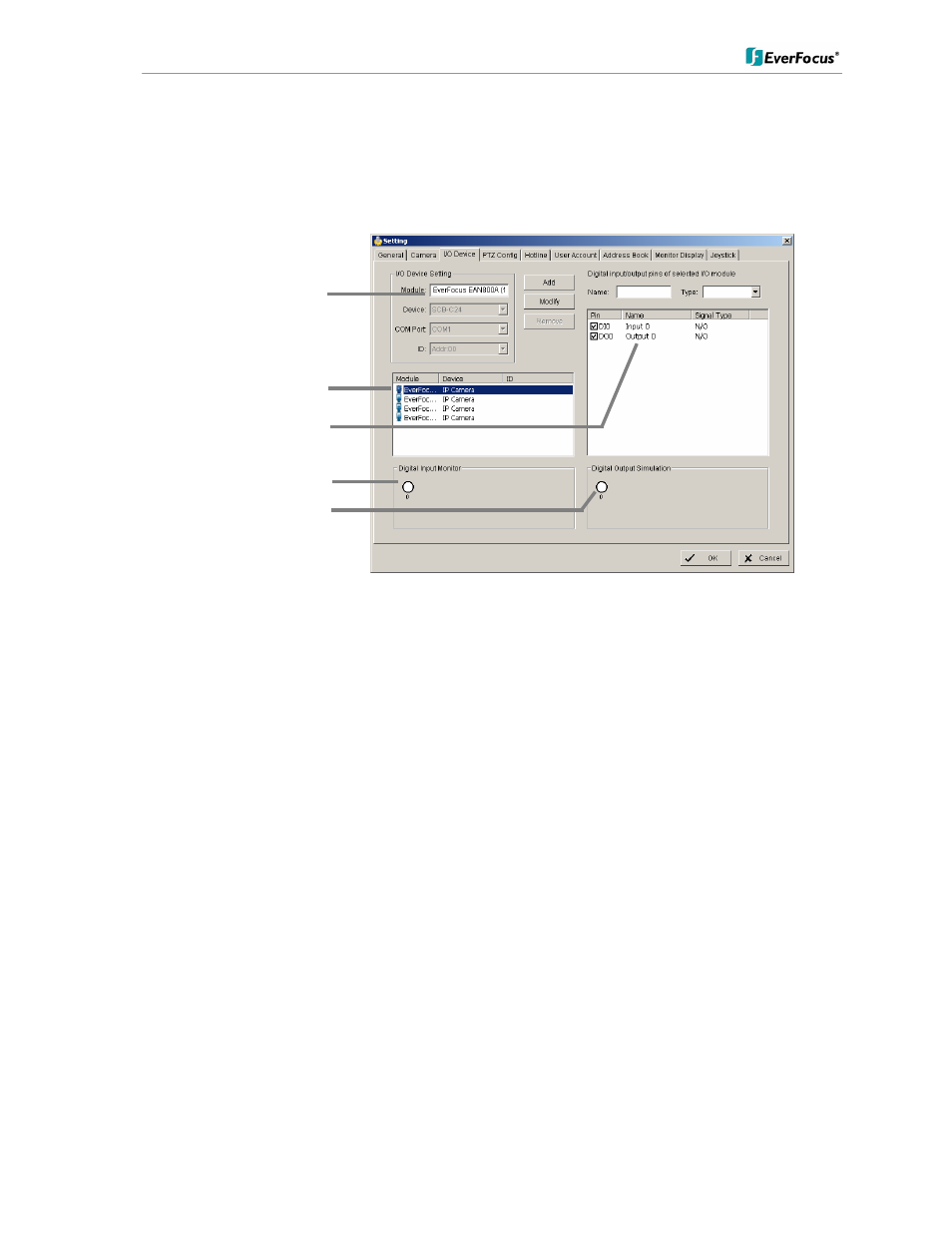
5.4.3 Setting - I/O Device
This menu defines parameters for digital inputs and outputs of connected IP devices.
The functionality depends on connected IP - devices.
Module Setting
Device name of selected IP device (as defined in CAMERA menu)
Add, Modify,
Remove,
Device, Com
port, ID
reserved functions for IP-serial converters
Device list
List with available IP-devices, which provide I/O function
Digital Input
Monitor
The selected input is turned on if the dot is in red. By triggering the digital
input device, the related icon will light up. This is used to check if the
device is correctly connected or not.
Digital Output
Simulation
The selected output is turned on if the dot is in red. By clicking on the
icon, you may trigger the digital device connecting to the system. This can
be used to test if the output device is correctly connected.
Digital input/output pins of selected I/O module
Name
Define the name of the device (input and output).
Type
Select the device type from the drop-down menu.
N/O
Normal Open.
N/C
Normal Close.
Device name
List of available devices
Input / Output list
Input monitor
Output simulator