Block diagram, 4 front card-edge interface – Grass Valley FIO-1901-TT User Manual
Page 6
GUIDE TO INSTALLATION AND OPERATION
2 | FIO-1901-TT
1.3
Block Diagram
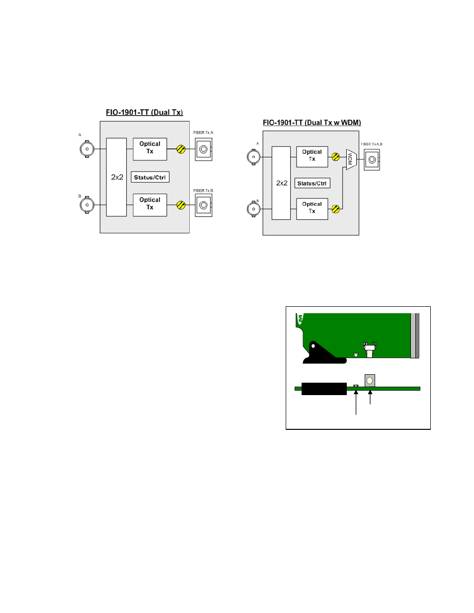
The following block diagrams show the functionality of the FIO-1901-TT. Both versions of the card (Dual Tx, and Dual
Tx with WDM) are illustrated.
Figure 1.1 Functional block diagram of the FIO-1901-TT
1.4 Front Card-edge Interface
The front card-edge of the FIO-1901-TT incorporates two elements:
• Status LED (see section 3.1)
• Select Button (see section 3.2)
Figure 1.2 Front card-edge layout
Se
le
ct
S
tat
us
FIO-1901-TT
Status LED
Select Button
This manual is related to the following products: