Grass Valley FIO-1901-TT User Manual
Page 15
GUIDE TO INSTALLATION AND OPERATION
FIO-1901-TT | 11
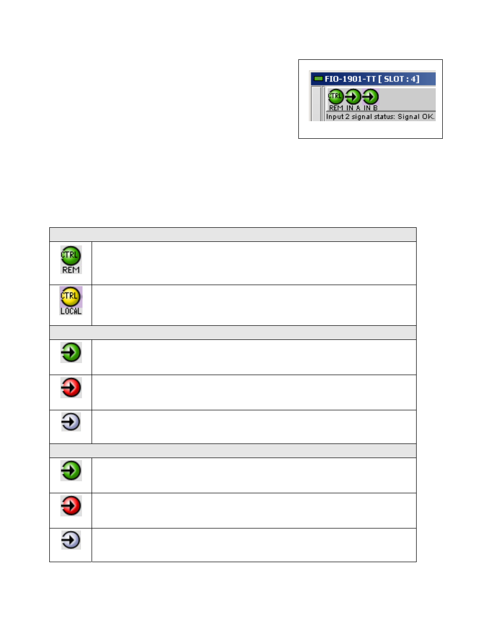
1. The top section displays icons on the left. These icons report the
status of some parameters associated with this FIO-1901-TT. Figure
3.3 shows the three icons that appear.
Move the mouse over an icon and a status message appears below the
icon providing additional information.
If there is an error, the error status message appears in the message
area without mouse-over.
• If there are multiple errors, the error messages cycle
• The icon whose status or error message is shown is highlighted
with a mauve background
The table below lists the various status icons that can appear, and how
they are to be interpreted.
• In cases where there is more than one possible interpretation, read the error message in the iControl window to
see which applies.
Table – iControl Status Icon interpretation
Icon #1 – Manual Card Configuration
(green)
Remote card control activated. The iControl interface can be used to operate the card
(yellow)
Local card control active, The card is being controlled using the Densité frame control
panel, as described in section 3.2. Any changes made using the iControl interface will have
no effect on the card.
Icon #2 – In A status
(green)
Signal detected and valid.
(red)
Input signal error
No rear
(grey)
No electrical input
Icon #3 – In B status
(green)
Signal detected and valid.
(red)
Input signal error
No rear
(grey)
No electrical input
Icon # 1
2
3
Figure 3.3 iControl Status Icons