To see a complete list of possible operating con – Grass Valley 2000GEN User Manual
Page 9
2000GEN Instruction Manual
9
Power Up
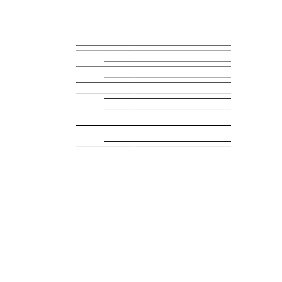
describes the meaning of the various states for the LED indications
on the front of the module (from left to right).
Table 1. Indicator LEDs and Conditions Indicated
LED
Indication
Condition
FAULT (red)
Off
Module functioning properly
On continuously
Module has detected internal fault
Long flash
Selected reference signal missing
COMM (yellow)
Off
No activity on frame bus
Long flash
Locate Module command received by the module from a remote control system
Short flash
Activity present on the frame communication bus
CONF (yellow)
Off
Module is in normal operating mode
On continuously
Module is initializing, changing operating modes or updating firmware
PWR (green)
Off
No power to module or module’s DC/DC converter failed
On continuously
Normal operation, module is powered
LOCKED (green)
Off
Signal phase unlocked
On continuously
Signal phase locked
NTSC (yellow)
Off
NTSC mode not selected
On continuously
NTSC mode selected
PAL -B (yellow)
Off
PAL-B mode not selected
On continuously
PAL-B mode selected
PAL-M (yellow)
Off
PAL-M mode not selected (currently not used)
On continuously
PAL-M mode selected (currently not used)
LOCK OUT (yellow)
Off
Jumper J8 is in the Remote position
On continuously
Jumper J8 is in the Local position, remote module configuration is locked out, mon-
itoring is still enabled