Power up, Operation indicator leds – Grass Valley 2000GEN User Manual
Page 8
8
2000GEN Instruction Manual
Power Up
Power Up
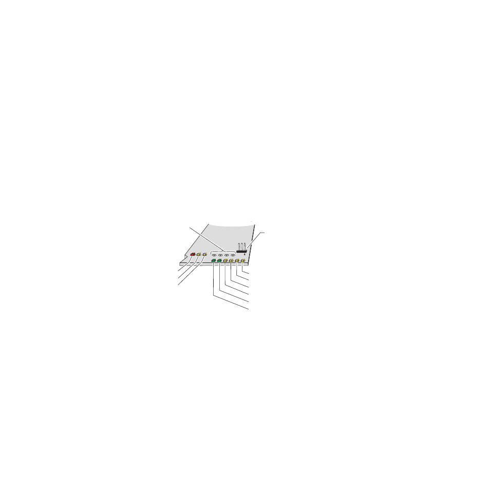
The on-board LED indicators are illustrated in
. Upon power-up,
the green PWR LED should light and the yellow CONF LED should illumi-
nate for the duration of module initialization.
Operation Indicator LEDs
After initialization, the green on-board PWR LED should light to indicate
correct power is present. Power can be measured at the indicated
testpoints.
Set the jumper at J8 to
Remote
during configuration (LOCK OUT LED
should be off). When remote configuration is complete, the jumper can be
set to local to lock out any further changes but still allow remote moni-
toring of the module if desired.
Refer to
to see a complete list of possible operating con-
ditions and the resulting indicator status.
Figure 3. LEDs and Configuration Switches
Communication (COMM) yellow
Configuration (CONF) yellow
FAULT red
Remote control
lockout jumper, J8
(Local = Pins 1 and 2,
Remote = Pins 2 and 3)
Testpoints
+5V, +3.3V, +2.5V, -5V
Power OK (PWR) green
Remote LOCK OUT yellow
PAL M yellow
PAL B yellow
NTSC yellow
Signal Lock LOCKED green
8172-02