Ensemble Designs 6010 Four Channel 24-bit Audio ADC User Manual
Page 7
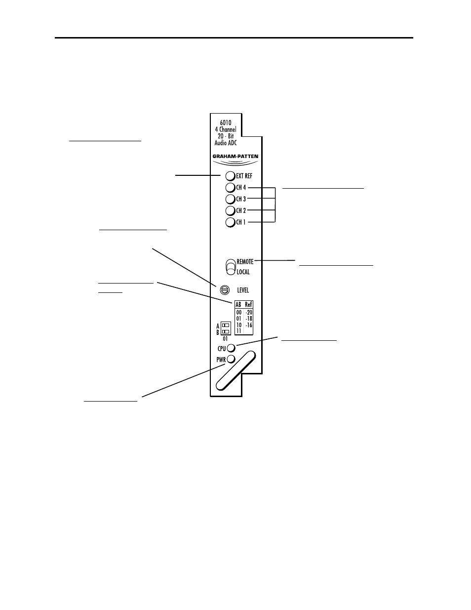
Front Panel Controls and Indicators
Each front edge indicator and switch setting is explained in the diagram below:
Model 6010 Four Channel 20-bit Audio ADC
6010-7
Remote/Local switch:
Set to the mode you
will be using.
EXT REF green LED:
ON indicates valid external
reference signal is present.
OFF indicates the external
reference is missing or invalid.
Pwr green LED:
Indicates the presence (ON) or
absence (OFF) of power (+5V).
CPU green LED:
OFF:
A power fault or halted CPU
ON:
A halted CPU
FAST BLINK:
CPU Run error
SLOW BLINK:
System OK. (If SPI control is
active from the main frame
System Control Module, all
Run indicators will be syn-
chronized.).
CH 1-CH4 green LEDs:
ON indicates analog input signal
peaks are reaching reference level.
OFF indicates the input signal
peaks are not reaching the
reference level.
REF -20/-18/-16
switch:
Set to the desired
digital reference
output level.
Select:
00 for -20 dBFS
01 for -18 dBFS
10 for -16 dBFS
LEVEL Adjustment:
Adjusts all four analog
inputs equally.
- 5130 Digital to Analog Composite Converter with Digital DA (11 pages)
- 5125 Dual Digital Video Distribution Amplifiers (12 pages)
- 7450 HD Protection Switch (43 pages)
- 5420 SD Logo Inserter (26 pages)
- 5410 Dual Sync Generator and Test Signal Generator with HD Tri-Level Sync (42 pages)
- 7925 Dual HD Downconverter (42 pages)
- 5475 Digital Noise Reducer Sub Module for 5470 (32 pages)
- 9110 3G / HD / SD / ASI Reclocking Distribution Amplifier (27 pages)
- 7420 HD/SD Logo Inserter (40 pages)
- 7420 HD/SD Logo Inserter (36 pages)
- 9465 3G Sync Changeover Switch (38 pages)
- 7600 HD/SD Embedder/Disembedder (30 pages)
- 7550 HD Legalizer (42 pages)
- 9550 3G / HD / SD Video Processing Frame Synchronizer (70 pages)
- 7920 HD Downconverter (47 pages)
- 5330 & 6330 Analog to Digital Video Converter and Embedder (76 pages)
- 9455 3G Clean and Quiet Protection Switch (64 pages)
- 4500 ASI and SMPTE 310M Converter and MPEG Transport Processor (32 pages)
- 5140 Analog EQ DA (12 pages)
- 5150 DA for Analog Video, AES and Tri-Level Sync (12 pages)
- 5155 Dual Analog Video, TLS, AES DA (12 pages)
- 9440 Flexible Matrix Router for 3G / HD / SD / ASI (138 pages)
- 5385 Analog Composite to Digital Converter (16 pages)
- 5365 Four Channel Analog to Digital Video Converters and Embedders (24 pages)
- 4110 ASI Distribution Amplifier (11 pages)
- 6030 Video-Reference AES/ Word Clock Generator (15 pages)
- 6040 Tracking Audio Delay (34 pages)
- 7405 HD Test Signal Generator (20 pages)
- 7410 Quad HD Tri-Level Sync Generator (16 pages)
- 6600 Series Analog Audio DAs and Frame Models 6601, 6601R and Frame 6600 (16 pages)
- 6020 Four Channel 24-bit Audio DAC (26 pages)
- BrightEye 20 Analog and Digital Audio Embedder or Disembedder (21 pages)
- 9670 Audio Automatic Gain and Loudness Control and 9690 Audio Compliance and Monitoring Software (18 pages)
- 9670 Audio Automatic Gain and Loudness Control and 9690 Audio Compliance and Monitoring Software (32 pages)
- 7400 HD/SD Test Signal and Sync Pulse Generator (82 pages)
- BrightEye 46 3G/HD/SD/ASI Electrical to Optical Converter (16 pages)
- BrightEye 70 HD/SD AES Embedder/Disembedder (26 pages)
- BrightEye 71-F HD/SD 8 Channel Analog Audio Embedder/Disembedder (27 pages)
- BrightEye 81-F Optical to HDMI and 3G / HD / SD SDI Electrical Converter (27 pages)
- BrightEye 72-F SDI to HDMI Converter, Color Corrector and Broadcast Confidence Monitor (40 pages)
- BrightEye NXT 430 and NXT 415 Compact Video Routers (132 pages)
- BrightEye 92-A HD Downconverter with Analog Audio (41 pages)
- BrightEye 83-F HDMI to Optical and Electrical 3G / HD / SD SDI Converter (26 pages)
- BrightEye 3 Analog to SDI Converter with TBC and Frame Sync (22 pages)