Eneo VHM/ZLB-W User Manual
Page 21
S
H
F
g
A
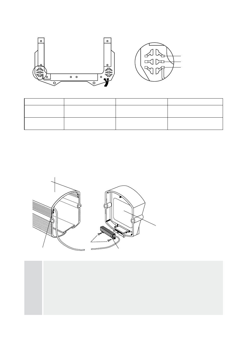
6.2 Assembling of PTC heater kit VHM/H220 230V (Art. No. 71301)
and VHM/H24 (Art. No. 71601)
F
The heater is screwed directly onto housing front section
F. To do this, first remove the front section
from the housing by unscrewing the two 4mm socket head screws.
H, g
Heating element
H is mounted at the required location using 3x 6mm self-tapping cross recessed head
screws
g.
S
A duct
S is provided in the housing profile for feeding the power supply cable to the power supply
terminal board.
Note
During the electrical connectioon at cable distributors, and/or power supply unit it is to be made certain
that the heater tension agrees with the input voltage.
Voltage
Solder bridge A
Solder bridge B
Solder bridge C
4V (factory default)
A on both sides
(right/left) open
B on both sides
(right/left) connected
C on both sides
(right/left) open
V configuration
A on both sides
(right/left) connected
B on both sides
(right/left) open
C on both sides
(right/left) connected
6.1.1 Configuring the factory default 24V heater for 12V operation
(VHM-ZLB-W and VHM-ZLKCB-W)
left
right
A
B
C