Eneo VHM/ZLB-W User Manual
Page 18
8
M
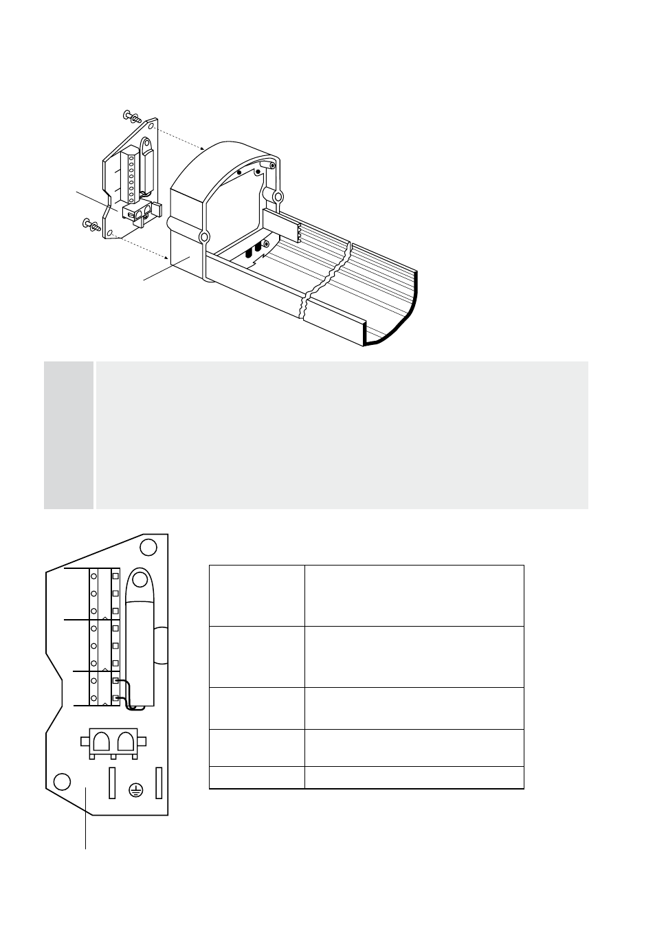
The assembly is installed in a vertical position in housing centre frame
M.
P, e
Terminal board
P is screwed into the stud bolts as shown in the diagram using the self-tapping screws e
(and washers) provided.
Note
When wiring up the unit, care must be taken to ensure that mains power supply cables L and N are
connected to the correct terminals. The earth wire is connected to the PE terminal.
Note
When connecting and operating the camera and heater, care must be taken to ensure the same
operating voltage and the permitted output. The making current for the PTC heaters can be more than
0 times the rated current.
5. Assembling and connecting the VHM/KV1 terminal board
(Art. No. 79609)
Terminal
Terminal
Terminal 3
Ground / Mains power supply cable (PE)
Mains power supply voltage (L)
Mains power supply voltage (N)
Terminal 4
Terminal 5
Terminal 6
Ground / camera (PE)
Camera 30VAC (N)
Camera 30VAC (L)
Terminal 7
Terminal 8
Bridges (thermostatic switches)
HEATER terminal
Heating ( pin AMP connector pre-mounted
on the heater)
Terminals 0-
Ground plug-in points
1
2
3
4
5
6
7
8
PE
L1
N
PE
N
L1
S
TA
T
MAINS
HEATER
PE
11
10
H
PE
L1
N
PE
N
L1
ST
AT
MAINS
PE
11
10
1
2
3
4
5
6
7
8
9
M
P
e
e