Dvim33c, Optional wall switch or thermostat, Fan wiring diagram – Archgard 31-DVIM33C User Manual
Page 19
31-DVIM33C
19
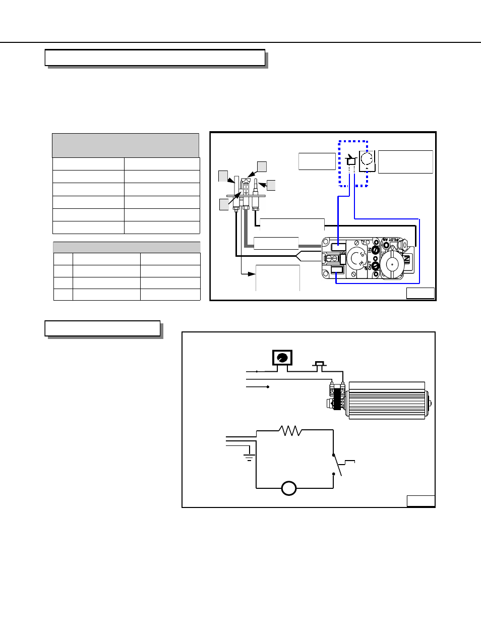
If a wall mounted switch or a wall mounted thermostat is desired, Archgard recommends that the device be
wired as shown in the diagram below.
NOTE: Archgard Industries does not manufacture or sell any type of wall switch or wall thermostat and will not
extend warranty to them
OPTIONAL WALL SWITCH OR THERMOSTAT
A
ELECTRODE
N/A
B
THERMOPILE
# 308-0056
C
PILOT HOOD
N/A
D
THERMOCOUPLE
# 308--0122
PILOT ASSEMBLY
Thermostat/wall switch wire table
Recommended max length for two wires
.
Wire Size
Max. Length
14 GA.
50’ (15.24 M)
16 GA.
32’ (9.75 M)
18 GA.
20’ (6.9 M)
20 GA.
12’ (3.65 M)
22 GA.
9’ (2.74 M)
M
SPEED
110F (43ºC) N.O.
THERMAL SNAP
CONVECTION BLOWER
LINE
GROUND
NEUTRAL
To Appliance
120 VAC
white
black
SPEED
LINE
GROUND
NEUTRAL
110ºF (43ºC)
N.O.
CONVECTION
BLOWER
white
black
green
OPTIONAL
REMOTE SWITCH
ON / OFF
WIRE TO
PIEZO
B
A
C
D
SUPPLY TUBE
THERMOCOUPLE
T
THT
TH
FAN WIRING DIAGRAM
The 31-DVIM33 comes complete with:
Temperature activated fan - (#RF-305-0024)
Solid State speed control. - (#305-0013)
6ft power cord
NOTE: This appliance, when installed, must be electrically grounded in accordance with local codes or, in the
absence of local codes, with the National Electrical Code, ANSI/NFPA 70, or the Canadian Electrical code,
CSA C22.1.
The fan disc is factory set to close
the circuit to the fan speed control at
110
0
F (43
0
C) and will turn off the
fan when the temperature falls below
80
0
F (27
0
C).
Fig. 19-B
Fig. 19-A