Dvt30n – Archgard 72-DVT30N User Manual
Page 44
72-DVT30N
44
1.
Open the lower grills (louvers).
2.
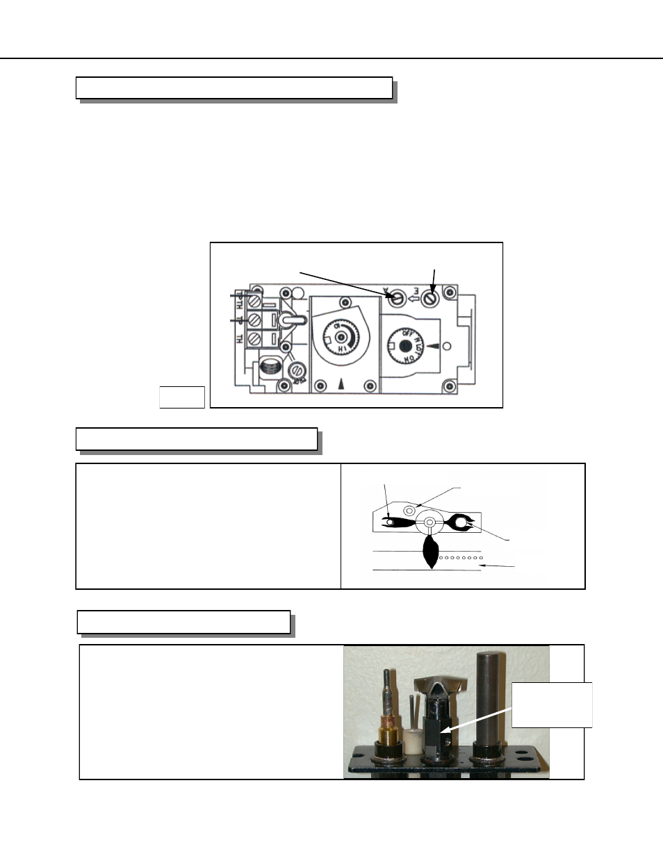
The pressure test taps are located on the valve. The taps are located in the gas valve
front face. The inlet is marked ‘IN’ and the outlet is marked ‘OUT’. See Fig.1.
3.
Loosen the set screw inside the tap with a 1/8” (3 mm) wide flat screw driver.
4.
Connect a 1/4” (6 mm) rubber tube to the tap post and a manometer.
5.
Verify the readings obtained are within specs (as shown on the appliance rating plate)
6.
Be sure to tighten the set screw inside the tap after you are finish taking pressure
readings.
7.
Check for leaks.
CHECKING INLET AND OUTLET GAS PRESSURE
OUT (manifold)
IN (inlet)
Fig. 1
CHECKING AND ADJUSTING PILOT
CONVERTIBLE PILOT ORIFICE
The pilot assembly is convertible to the type
of gas being used, simply unscrew the body
by using a 7/16” (11 mm) wrench turn a 1/4
open then push the small metal tab across
to the other side of the body and retighten.
Call your local Authorized Archgard
Dealer to purchase the correct fuel con-
version kit for your gas appliance.
7/16” (11 mm)
WRENCH
(HERE)
The pilot flame should have the char-
acteristic as shown in the illustration to
the right. The flame should not have
yellow tips but should engulf the ther-
mocouple and thermopile. It can be
adjusted be turning the screw marked
“pilot” on the control valve.
Thermopile
Burner Ports
Electrode
Thermocouple