Dvt30n – Archgard 72-DVT30N User Manual
Page 20
72-DVT30N
20
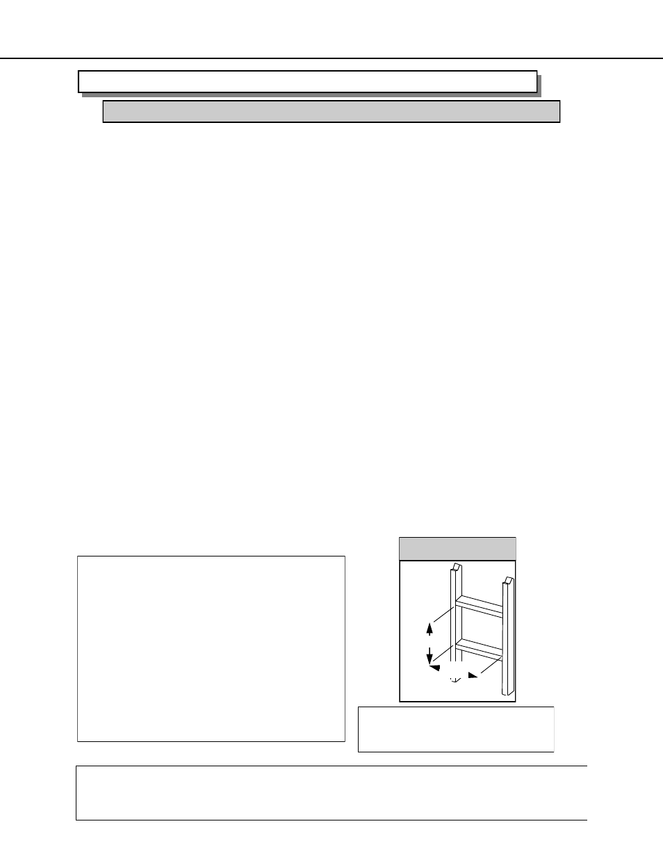
1. Place the Optima 72 in the framing. Locate the centerline of the termination and mark the wall.
Cut an 11” x 10” (279mm x 254mm) hole in the wall. NOTE: a 2” (50mm) x 1-½” (13mm)
around the 7” (178mm) liner is required. See Fig.1 for termination framing.
2. Locate the Horizontal termination head and the 4” (101mm) flexible exhaust pipe, and “DRY”
slip the exhaust pipe over the 4” (101mm) exhaust port on the termination head. Un-slip the
“DRY” connection and apply high temperature sealant to the 4” (101mm) flexible exhaust port
and reattach to the 4” (101mm) exhaust connection on the termination head and fasten with
three screws on the pre-drilled locations. Repeat this same process with the 7” (178mm) flexi-
ble liner.
3. Locate the wall sleeve and cut to the thickness of the wall and slip it through the wall.
4. Locate the Firestop and secure in place with 4 screws.
5. Pull / Straighten the inner 4” (101mm) exhaust pipe to its maximum capacity and “wrap” the
spring spacers at every change of direction and every 3ft (914mm) if longer lengths of flexible
liner is used. Next pull the 7” (178mm) intake liner over the 4” (101mm) exhaust liner.
NOTE: Take care when “pulling / stretching out the liners; inspect for “breaks” in the liners or
in the termination head. Any “breaks” in the venting system will cause poor flame and im-
proper combustion.
6. Slip the assembled liner and termination head through the wall sleeve and make sure the ter-
mination cap faces up and fasten the termination head to the wall with 4 screws provided with
the kit.
NOTE: If installing the termination head to vinyl or wood siding a Vinyl Siding Deflector (999-
DV-VSD) is required. The 999-DV-VSD must be set on top of the horizontal termination cap
(fin side out) and then the two screws holding the termination cap are used to secure the ter-
mination head and 999-DV-VSD.
7. Apply high temperature sealant over the fireplace’s inner exhaust collar and slip the
4” (101mm) inner flexible exhaust liner down over it and attach the connection with three
screws.
8. Repeat with the 7” (178mm) liner.
9. Apply a bead of all weather silicone (not provided) around the termination head & house to
prevent water from entering in.
INSTALLATION PROCEDURES - ARCHGARD DIRECT VENT (FLEX) SYSTEM
VENTING - HORIZONTALLY USING FLEXIBLE DIRECT VENT SYSTEMS
NOTES:
If installing a Vinyl Siding Deflector (999-
DV-VSD) attach the 999-DV-VSD to the
front top of the horizontal termination head
“fin side out” to ensure the termination
head is not recessed into the siding.
Horizontal sections of pipe MUST be sup-
ported every 3’ (914mm).
Spacers shall be installed at every change
of direction and every 3’ (914mm) if using
additional flexible pipe.
IMPORTANT: Do not locate termination head where excessive snow or ice buildup may occur.
Check termination head area after every snow fall, and clear if necessary to prevent blockage.
If using snow blowers, make sure snow is not directed at the termination head.
NOTE: Be sure to include
1/4” (6mm) rise per foot of
horizontal length.
10”
(254 mm)
Termination Framing
11” (279 mm)
Fig.1