Dvt30n – Archgard 72-DVT30N User Manual
Page 15
72-DVT30N
15
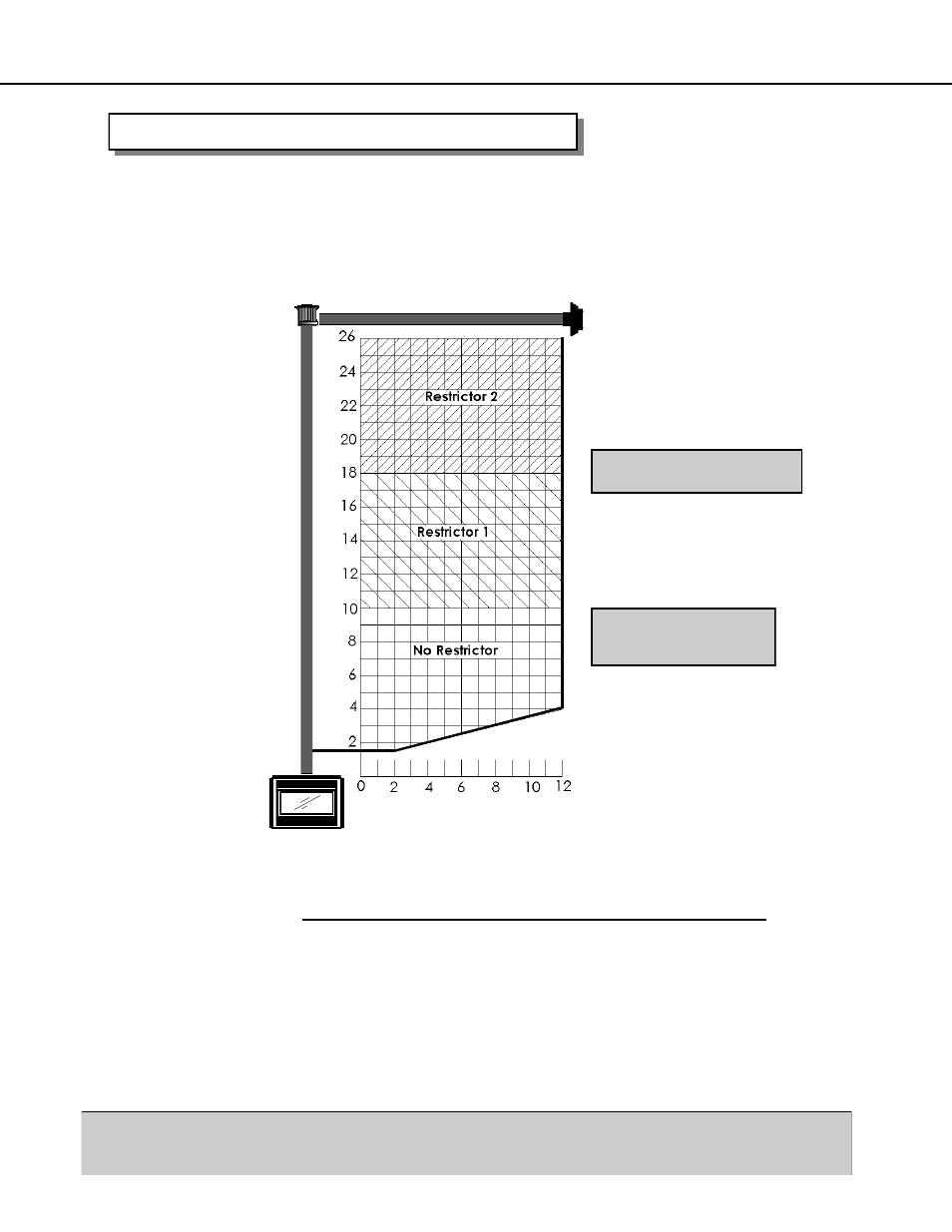
VENTING - VERTICAL TERMINATION CHART
Chart is for one 90° bend, with a 1/4” (6 mm) minimum vertical rise per running foot of
horizontal length.
For each additional 90° or two 45°, add one foot of vertical height.
Maximum three 90º bends, or equivalent allowed in the system.
Minimum 2 ft (610 mm) straight length between bends.
The appliance will not function without being connected to a proper venting system. This
appliance may only use direct vent system approved by Archgard, or Simpson Dura-Vent
direct vent systems with Archgard 999-DV-SDA adapter.
Please strictly follow the venting instructions for optimum performance
from the appliance and to avoid sooting and/or service calls.
VENTING ABOVE ROOF OF THE HOUSE USING A VERTICAL TERMINATION
Use Simpson Dura-Vent listed direct vent system caps for all vertical vent termination
applications (through the roof).
.6
10
m
1.
22
m
1.
83
m
2.
44
m
3.
05
m
3.
66
m
7.93 M
7.32 M
6.71 M
6.10 M
5.49 M
4.88 M
4.27 M
3.66 M
3.05 M
2.44 M
1.83 M
1.22 M
610 mm
V
E
R
T
I
C
A
L
H
E
I
G
H
T
VENTING CHART
HORIZONTAL LENGTH
NOTE: NO INSTALLATIONS
ARE PERMITTED OUTSIDE
OF THIS RANGE
SEE PAGE 14 FOR RESTRICTOR
SHAPE & PLACEMENT