No yes yes – Airmar P52 with Kick-up Bracket 20-035 User Manual
Page 3
3
Setting the Bracket Release Point
There is considerable force on the bracket during normal
operation. The amount of force is proportional to the drag which is
created by the:
• Sensor—shape, size, weight, and amount of projection
below the transom.
• Speed—the square of the speed of the boat.
A larger and heavier transducer or TRIDUCER
®
multisensor
creates more drag as does a higher boat speed. For example, the
drag at 40kn (46MPH) is 4 times that at 20kn (23MPH).
Set the springs in the appropriate notches on the pivot arms (see
Figure 7).
• Middle or lower notches if the top speed of the boat is more
than 30kn (34MPH).
Release Line
CAUTION: Be sure that both ends of the line are well secured to
eliminate the possibility of becoming entangled in the propeller.
To facilitate raising the sensor to the “up” (released) position, a
line can be attached to the bracket’s crossbar (see Figures 7 and
1). An upward jerk on this line will release the bracket.
Cable Routing
CAUTION: Do not remove the connector to ease cable routing. If
the cable must be cut and spliced, use Airmar’s splash-proof
Junction Box No. 33-035 and follow the instructions provided.
Removing the waterproof connector or cutting the cable, except
when using a water-tight junction box, will void the sensor
warranty.
Route the sensor cable(s) over the transom, through a drain hole,
or through a new hole drilled in the transom above the waterline.
1. If a hole must be drilled, choose a location well above the
waterline. Check for obstructions such as trim tabs, pumps, or
wiring inside the hull. Mark the location with a pencil. Drill a hole
through the transom using a 20mm or 13/16” hole saw or spade
bit (to accommodate the connector).
2. Route the cable(s) over or through the transom. Be sure the
cable is between the cross bar and the transom (see photo
on page 1).
3. On the outside of the hull secure the cable(s) against the
transom using the cable clamps. Position a cable clamp 50mm
(2") above the bracket and mark the screw hole with a pencil
(see Figure 4).
4. Position the second cable clamp halfway between the first
clamp and the cable hole. Mark this mounting hole. If there are
two cables, repeat this step.
5. If a hole has been drilled through the transom, open the
appropriate slot(s) in the cable cover (see Figure 8). The cable
cover can accommodate two cables when there are separate
cables for depth and speed/temperature functions. Position the
cover over the cable(s) where it enters the hull. Mark the two
mounting holes.
6. At each of the marked locations, use a 3mm or 1/8" bit to drill a
hole 10mm (3/8") deep.
7. Apply marine sealant to the threads of the #6 x 1/2" (13mm)
self-tapping screws to prevent water from seeping into the
transom. If a hole has been drilled through the transom, apply
marine sealant to the space around the cable leading through
the transom.
8. Position the two cable clamps and screw them in place. If used,
push the cable cover over the cable(s) and screw it in place.
9. Route the cable(s) to the instrument(s), being careful not to tear
the cable jacket when passing it through the bulkhead(s) and
other parts of the boat. To reduce electrical interference,
separate the sensor cable(s) from other electrical wiring and
sources of noise. Coil any excess cable and secure it in place
with zip-ties to prevent damage.
10.Refer to the echosounder owner’s manual(s) to connect the
sensor to the instrument(s).
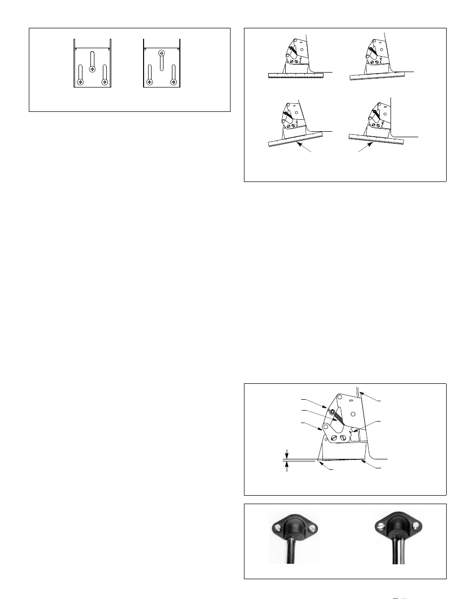
Figure 6. Transducer angle adjustment (P37 shown)
NO
NO
YES
YES
parallel
slight angle
angle too severe
Figure 5. Mounting the bracket
correct
incorrect
(cannot adjust)
Figure 8. Cable cover
Figure 7. Transducer angle & release point setting (P37 shown)
1-3mm (1/16-1/8")
bow
stern
pivot arm
notch
spring
cross bar
cable