Airmar B744V User Manual
Installation instructions, Junction box kit, Applications
17
-0
33
-0
2 re
v.
07
12
/14
/10
Applications
• These instructions are for a replacement speed/temperature
insert only. Installing a new insert will NOT solve problems with
depth sounding or fish finding.
• Determine which instructions to follow, either A or B, by looking
at your multisensor. If your multisensor has one cable, follow
instructions A on page 2. If your multisensor has two cables—
one from the depth transducer and one from the speed/
temperature insert—follow instructions B on page 3.
• If these instructions are followed carefully:
• The connections will not corrode
• The strain relief grommets will be water resistant and provide
excellent cable retention.
Before Installing
1. Be sure your new speed/temperature insert is the correct
replacement. Compare the length of the new insert with the
original insert (ignore the cable). If the new insert is more than
3mm (1/8") longer or shorter than the original insert, return it. To
obtain the correct insert, see “ Replacement Parts” on the back
of your multisensor’s owner’s guide.
2. Check the multisensor’s connector at the echosounder for
corrosion. If the connector’s pins are corroded, clean them.
Then test the multisensor to see if the problem has been
corrected.
3. Check the speed and temperature functions of the new insert.
Connect it to the echosounder and spin the paddlewheel.
Check for a reading of several knots. Check for the approximate
air temperature. If there is no reading(s), check the connection
and repeat the test. If there is still no reading(s) or it is
inaccurate, return the product to your place of purchase.
Tools & Materials
Safety goggles
Dust mask
Pencil
Drill
Drill bit: 3mm or 1/8"
Screwdrivers: Phillips and blade
Box-cutter knife (zip-cable installation)
Cutting pliers
Masking tape
Marker
Wire strippers
Alcohol
Crimping pliers (nine or ten-wire cables)
Anti-fouling paint (water-based) (mandatory in salt water)
Silicone lubricant or petroleum jelly
Mounting Location
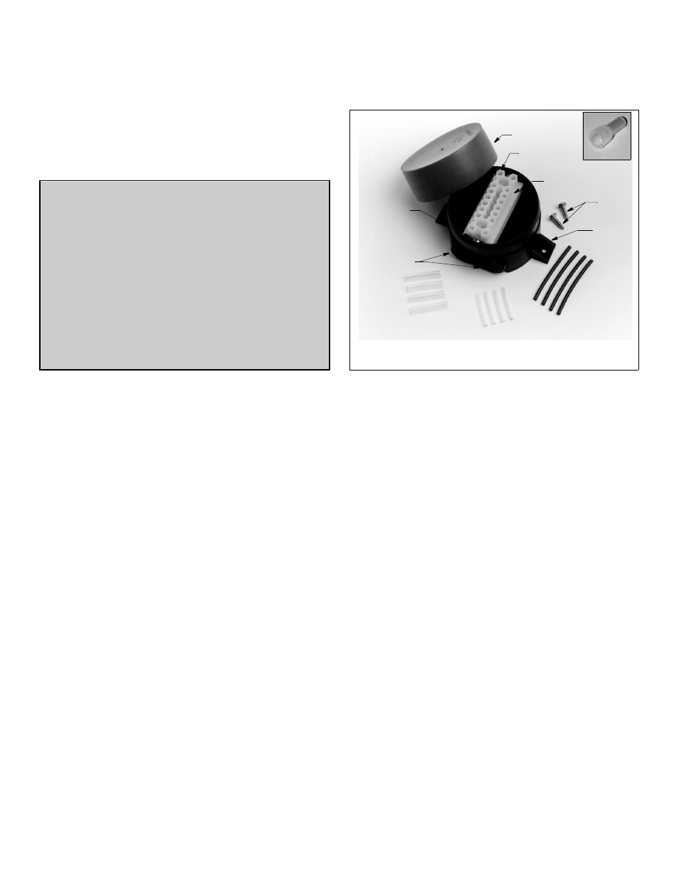
1. Remove the red cap from the junction box and set the contents
aside (see Figure 1).
2. Select a convenient dry mounting location along the
multisensor’s cable route, preferably 1–1.5 m (3–5') from the
multisensor but no more than 3m (10').
3. Position the junction box so the grommets are easily accessible
to the cable. Mark the location of the mounting holes.
4. At the marked location, drill two 3mm or 1/8" holes
approximately 10mm (3/8") deep. Do not fasten the junction
box in place at this time.
INSTALLATION INSTRUCTIONS
connector
black sleeving
large diameter
sleeving
small diameter
sleeving
terminal block
tab (2)
grommet (4)
Figure 1. Junction box and contents
terminal
terminal screw
mounting screws
mounting
block
screws
(16)
screw (2)
cap
Copyright © 2002, 2009 Airmar Technology Corp.
WARNING: Always wear safety goggles and a dust
mask when installing to avoid personal injury.
CAUTION: High Voltage Charge
The depth transducer may be storing a high voltage
charge. Accidental discharge could destroy the speed
sensor.
IMPORTANT: Read the instructions completely
before proceeding with the installation. These
instructions supersede any other instructions in your
instrument manual if they differ.
Junction Box Kit
for Replacement Speed/Temperature Insert
Models: B44V, B66VL, B744V, B744VC, B744VL, B744VLC