Airmar M192—Survey User Manual
Installation instructions, M192-nav transducer, Warning : never use solvents
WARNING: NEVER USE SOLVENTS!
Cleaners, gasoline, paints, sealants, and other products may
contain strong solvents, such as acetone, which can attack many
plastics dramatically reducing their strength.
IMPORTANT: Please read the instructions completely before
proceeding with the installation. These directions supersede
instructions in your instrument manual if they differ.
INSTALLATION INSTRUCTIONS
17-
174-01
rev. 1
2/
99
M192-NAV Transducer
Installed in Lloyd’s Type Approved, Tank, CS235
Tools and Materials Needed
Water-based antifouling paint (
mandatory in salt water)
Cable gland
Junction box
Underwater lubricant such as Aqualube
®
Hex wrench: 8M
Marine sealant
NOTE: The terms tank and housing are used interchangeably.
Antifouling Paint
Surfaces exposed to salt water must be coated with
antifouling paint. Paint the housing with an appropriate
antifouling, corrosion inhibiting coating. Use only water-
based antifouling paint on the radiating face of the
transducer. Never use ketone-based paint on the
transducer’s face since ketones can attack many plastics
possibly damaging the transducer. It is easier to apply
antifouling paint before installation, but allow for sufficient
drying time.
Installing the Transducer and Cable
Caution: Never pull, carry, or hold the transducer by the
cable as this may sever internal connections.
1. Inspect the transducer, cable, and connectors carefully
before installing. All parts must be clean and free of oil,
grease, paint, solvents, and other foreign material that
may hinder performance.
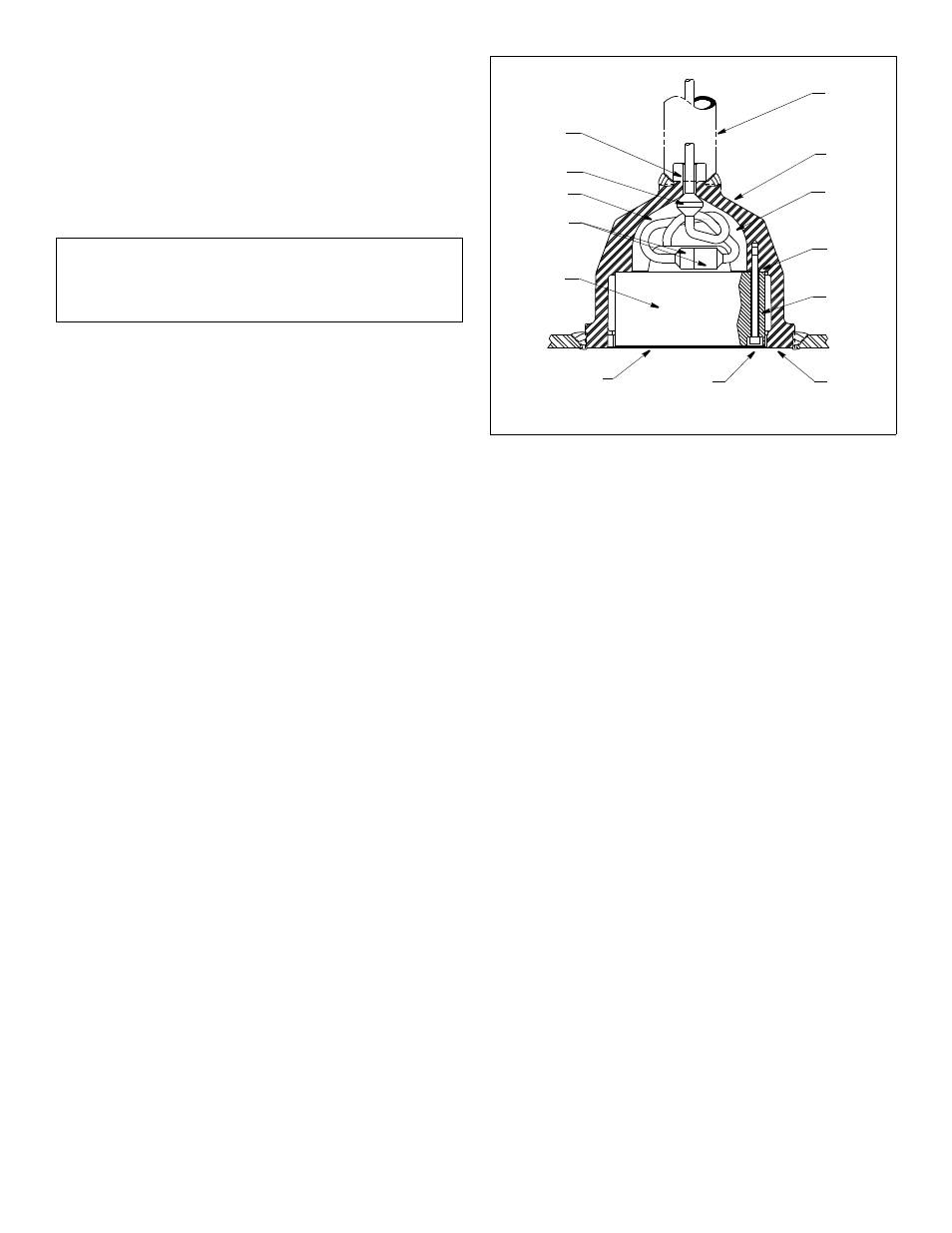
2. Pull the tagged end of the transducer cable
(P/N 22-136-01) through the housing cable passage
and the seamless pipe until the cable stop is seated
firmly against the cable passage opening (see Figure 1).
Approximately 305mm (12") of cable will remain in the
housing with the male connector attached.
3. Use a suitable cable gland at the top of the pipe to
support and clamp the cable.
4. Secure the free end of the cable in a junction box
located in a dry, gas free environment within the ship.
Caution: The transducer’s mounting screws utilize
rubber retaining rings to hold the screws in place
during installation. Do not remove them.
5. Carefully push the socket head end of each mounting
screw into the counterbore of the transducer to fully
expose the threaded end of the screw. Sparingly apply
a uniform coat of Aqualube
®
or other similar
underwater lubricant to the screw threads.
Caution: Lubrication is vital to the removal of these
screws should replacement of the transducer ever be
required.
6. Push the threaded end of each screw back into the
transducer until approximately 7mm (0.25") of the
lubricated threads are exposed and held in place by
the retaining ring.
7. While supporting the weight of the transducer, plug the
mating connectors together until they are fully
engaged. The connector faces must touch.
8. Slowly rotate the transducer approximately 1 to 2 turns
as it is raised into the housing to properly dress the
cable and joined connectors in the cable storage
cavity. The transducer face will be almost flush with the
flange of the housing when the cable is properly
stowed and the mounting screws are seated in the
threaded holes of the housing.
Figure 1. Installation
seamless
pipe
tank
cable
connectors
cable
cable
loop
storage
cavity
stop
transducer
rubber
retaining
ring (3)
mounting
screw (3)
radiating face
counterbore (3)
flange
cable
passage
(housing)