Airmar P52 with Kick-up Bracket 20-035 User Manual
Installation instructions owner’s guide, Transom mount, Transducer or triducer
17
-0
02
r
ev.
04
04
/12
/11
Transom Mount
with Kick-up Bracket 20-035
Transducer or TRIDUCER
®
Multisensor
Model: P52
Applications
• Not recommended for boat with large inboard engine(s).
• Good operation up to 40kn (46MPH).
Requires experimentation at higher speeds.
• Vertically orients the sound beam on hull with deadrise angle up
to 22
°
• Adjusts to transom angles up to 20
°.
Tools & Materials
Safety goggles
Dust mask
Water-based antifouling paint (mandatory in salt water)
Screwdrivers
Adjustable wrench
Pencil
Electric drill
Drill bits and hole saw or spade bit:
Bracket holes
4mm, #23, or 9/64"
Fiberglass hull
chamfer (preferred), 6mm, or 1/4"
Transom hole (optional)
20mm or 13/16"
Cable clamp holes
3mm or 1/8"
Masking tape
Marine sealant (suitable for below waterline)
Straight edge
Line (optional)
Zip-ties
Identifying Your Model
The model name is printed on the cable tag.
Antifouling Paint
Aquatic growth can accumulate rapidly on the sensor’s surface
reducing performance within weeks. Surfaces exposed to salt
water that do not interlock must be coated with antifouling paint.
Use water-based antifouling paint only. Never use ketone based
paint, since ketones can attack many types of plastic possibly
causing damage to the transducer. It may be easier to apply paint
before installing the sensor, but allow drying time. Reapply paint
every 6 months or at the beginning of each boating season.
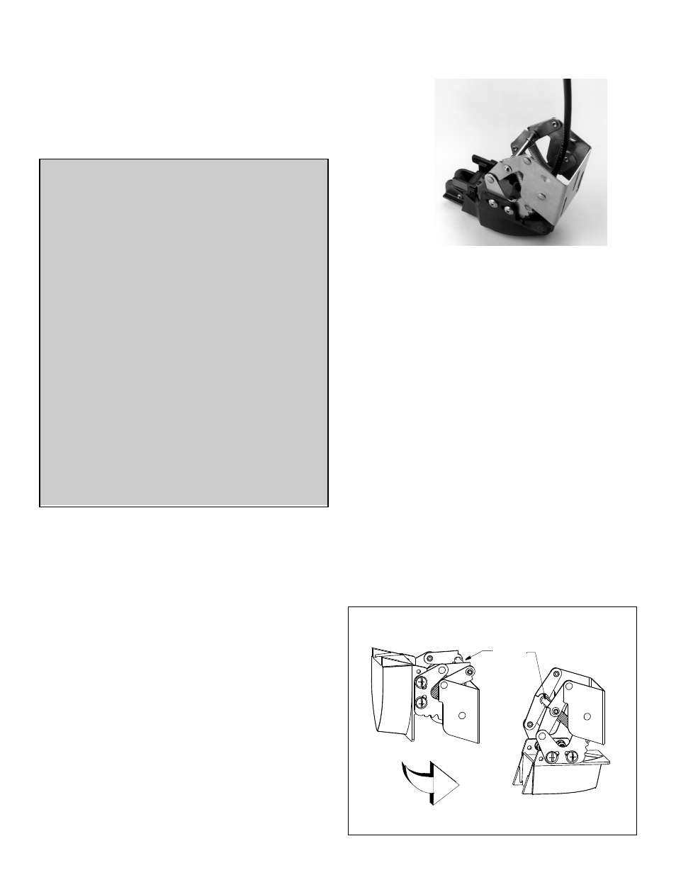
Assembling
1. The bracket is shipped in the “up” (released) position. Before
attaching the sensor, set the bracket in the “down” (operating)
position by grasping the cross bar and pulling outward in an arc
(see Figure 1).
2. Run the cable through the bracket between the cross bar and
the transom (see photo on front page).
3. Attach the sensor to the bracket with the four #10-32 x 5/8"
machine screws, washers, and lock nuts. Tighten the screws so
the sensor remains in place, but can be adjusted (see Figure 2).
P52—Place the bracket inside the mounting tabs (see photo on
front page).
P52 TRIDUCER® Multisensor
Figure 1. Bracket positions (P37 shown)
“up” (released)
“down” (operating)
cross bar
INSTALLATION INSTRUCTIONS
OWNER’S GUIDE &
Follow the precautions below for optimal product
performance and to reduce the risk of property
damage, personal injury, and/or death.
WARNING: Always wear safety goggles and a dust
mask when installing
WARNING: When the boat is placed in the water,
immediately check for leaks around the screws and
any other holes drilled in the hull.
CAUTION:
The bracket protects the sensor from frontal
impact only.
CAUTION: Never pull, carry, or hold the sensor by the
cable as this may sever internal connections.
CAUTION: Never strike the sensor.
CAUTION: Never use solvents. Cleaners, fuel, paint,
sealants, and other products may contain strong
solvents, such as acetone, which attack many plastics
greatly reducing their strength.
IMPORTANT: Please read the instructions completely
before proceeding with the installation. These
instructions supersede any other instructions in your
instrument manual if they differ.