Checking for leaks, Testing on the water, Antifouling paint – Airmar P65 User Manual
Page 3: Maintenance , repair & replacement
3
Cable Routing
CAUTION: Do not remove the connector to ease cable routing. If the
cable must be cut and spliced, use Airmar’s splash-proof Junction
Box No. 33-035 and follow the instructions provided. Removing the
waterproof connector or cutting the cable, except when using a
water-tight junction box, will void the sensor warranty.
Route the sensor cable over the transom, through a drain hole or
through a new hole drilled in the transom above the waterline.
1. If a hole must be drilled, choose a location well above the
waterline. Check for obstructions such as trim tabs, pumps or
wiring inside the hull. Mark the location with a pencil. Drill a hole
through the transom using 20mm or 13/16" bit to accommodate
the connector.
2. Route the cable over or through the transom.
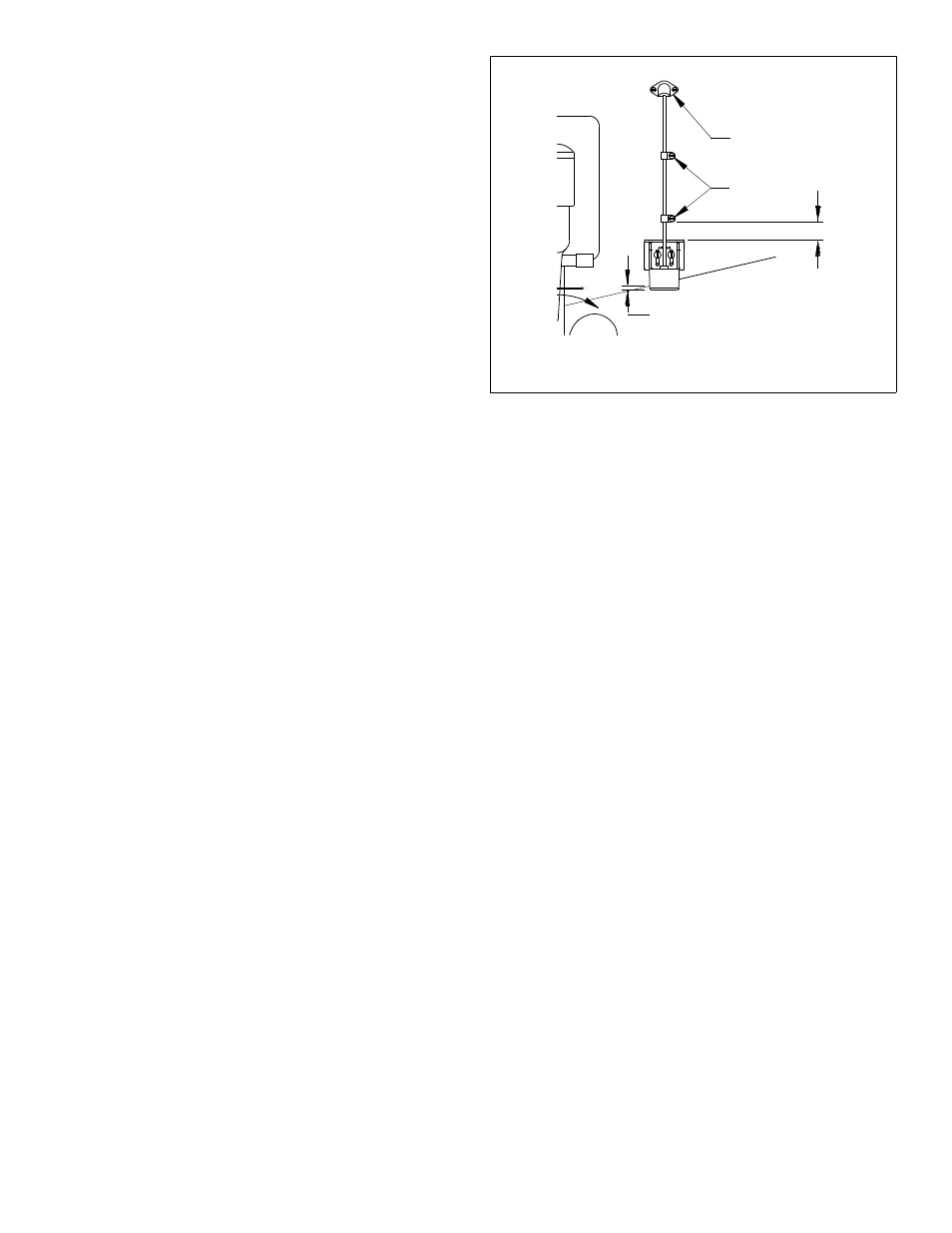
3. On the outside of the hull secure the cable against the transom
using the cable clamps. Position a cable clamp 50mm (2")
above the bracket and mark the mounting hole with a pencil
(see Figure 4).
4. Position the second cable clamp halfway between the first
clamp and the cable hole. Mark this mounting hole.
5. If a hole has been drilled in the transom, open the appropriate
slot in the cable cover. Position the cover over the cable where
it enters the hull. Mark the two screw holes.
6. At each of the marked locations, use a 3mm or 1/8" bit to drill a
hole 10mm (3/8") deep.
7. Apply marine sealant to the space around the cable and the
threads of the four #6 x 1/2" self-tapping screws to prevent
water from seeping into the transom. If you have drilled a hole
through the transom, apply marine sealant to the space around
the cable leading through the transom.
8. Position the two cable clamps and fasten them in place. If used,
push the cable cover over the cable and screw it in place.
9. Route the cable to the instrument being careful not to tear the
cable jacket when passing it through the bulkhead(s) and other
parts of the boat. To reduce electrical interference, separate the
sensor cable from other electrical wiring and “noise” sources.
Coil any excess cable and secure it in place using zip-ties to
prevent damage.
10.Refer to your echosounder owner’s manual to connect the
sensor to the instrument.
Checking for Leaks
When the boat is placed in the water, immediately check for
leaks around the screws and any holes drilled in the hull. Note
that very small leaks may not be readily observed. Do not leave
the boat in the water unchecked for more than three hours.
Testing on the Water
1. Become familiar with your echosounder’s performance at a
speed of 4kn (5MPH).
2. Gradually increase the boat speed and observe the gradual
decline in performance due to turbulent water flowing over the
transducer’s active surface.
3. If the decline in performance is sudden (not gradual), identify
the boat speed at which the onset occurred. Return the boat to
this speed, then gradually increase speed while making
moderate turns in both directions.
4. If the performance improves while turning to the side on which
the sensor is installed, the transducer’s position probably needs
adjustment. It is probably in aerated water.
To improve performance, try the following one at a time in the
order given.
a. Increase the sensor’s angle in the water. Review “Plastic
Shim.”
b. Move the sensor deeper into the water in increments of 3mm
(1/8").
c. Move the sensor closer to the centerline of the boat.
Fill unused screw holes with marine sealant.
NOTE: High-speed operation [above 35kn (40MPH)] may
require less projection in the water to improve performance and
reduce the chance that water pressure will cause the bracket to
release.
5. Calibration—To match the speed shown on the display to the
actual speed of the boat, you may need to calibrate the
instrument. Refer to your instrument owner’s manual.
Antifouling Paint
Aquatic growth can accumulate rapidly on the sensor’s surface
reducing performance within weeks. Surfaces exposed to salt
water that do not interlock must be coated with antifouling paint.
Use water-based antifouling paint only. Never use ketone based
paint since ketones can attack many types of plastic. Reapply
paint every 6 months or at the beginning of each boating season.
Maintenance, Repair & Replacement
Cleaning
Aquatic growth can accumulate rapidly reducing the sensor’s
performance within weeks. Clean the assembly with a soft cloth
and mild household detergent. If fouling occurs, use a stiff brush
or putty knife to remove the growth being careful to avoid making
scratches on the transducer face. In severe cases, wet sand the
surface with fine grade wet/dry paper.
If the paddlewheel becomes fouled or inoperable, it can be
removed for cleaning. Gently push back one retaining arm and
slide the shaft out. After cleaning, reinsert the shaft by pushing
back on the retaining arm. Be sure the shaft ends are secure in
the retaining arm notches.
Figure 4. Hull projection and cable installation
50mm (2")
cable cover
cable clamp
Hull projection:
3mm (1/8")