Pretest, Installation, Plastic shim – Airmar P65 User Manual
Page 2: Attaching the shim, Mounting & adjusting, Assembling, positioning, & hole drilling
2
Plastic Shim
• If you know the transom angle of your boat (see Figure 3):
• Standard transom (13° transom angle)—The bracket is
designed for a standard 13° transom angle, so the shim is
not needed for this installation.
• High Speed Boat—If your boat is capable of speeds above
30kn (35MPH), install the bracket with the shim, tapered end
down. This ensures that the paddlewheel will be immersed at
high speeds.
• Stepped transom and jet boats (3° transom angle) —Use
the shim with the tapered end down.
• Small aluminum and fiberglass boats (20° transom
angle)—Use the shim with the tapered end up.
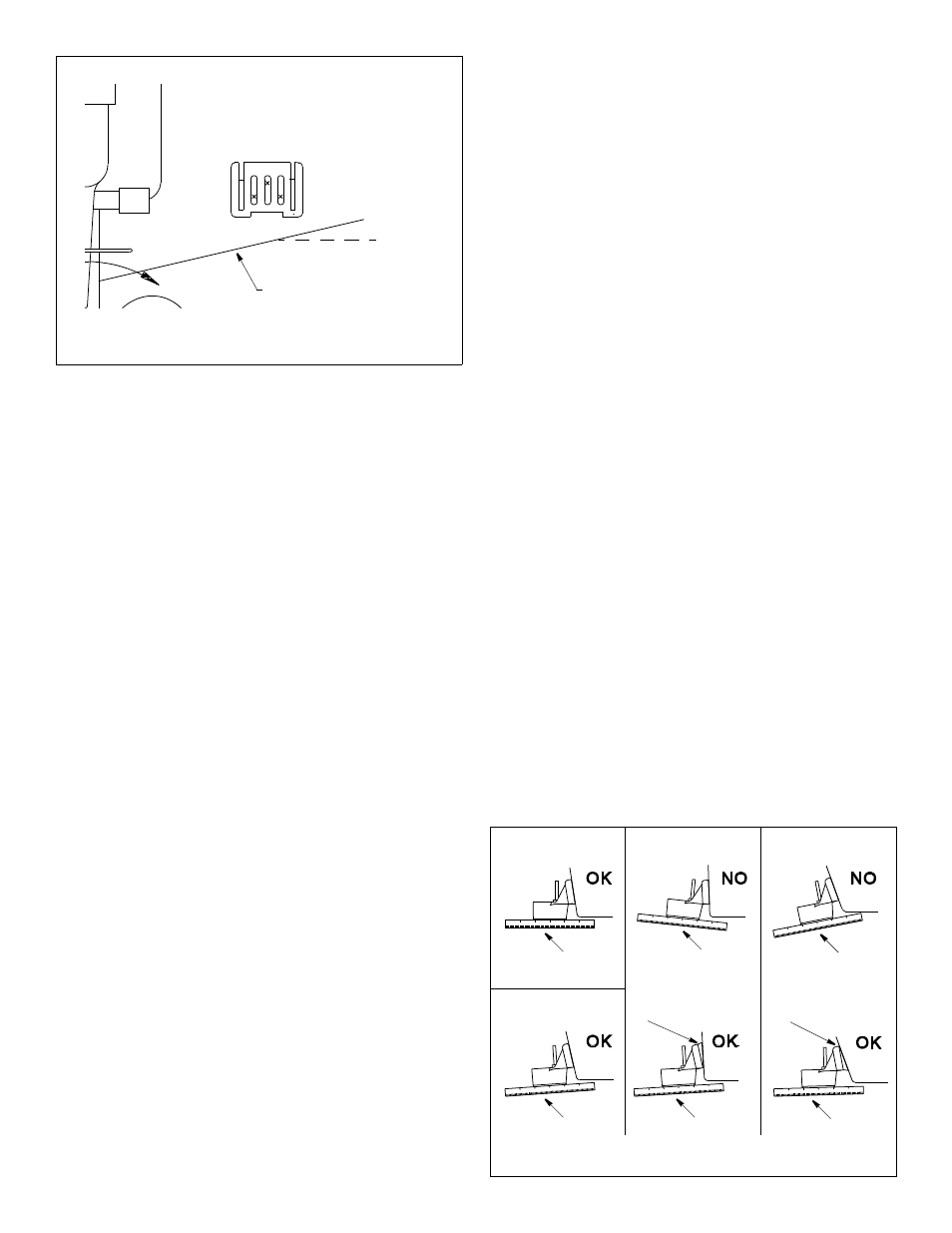
• If you do NOT know the transom angle of your boat:
To determine if the shim is needed, position the sensor at the
selected location. Using a straight edge, sight the underside of
the sensor relative to the underside of the hull. The trailing edge
of the sensor should be 1–3mm (1/16–1/8") below the leading
edge of the sensor or parallel to the bottom of the hull (see
Figure 3).
Attaching the Shim
Align the posts on the shim with the two holes in the bracket.
Snap the shim into place.
Mounting & Adjusting
1. Apply a marine sealant to the threads of the three #10 x 1-1/4"
self-tapping screws to prevent water seepage into the transom.
With the sensor attached to the bracket in the “up” position,
screw the bracket to the hull. Do not tighten the screws
completely at this time.
2. Lower the sensor until it snaps into place.
3. Using the vertical adjustment space on the bracket slots, slide
the sensor up or down to provide a projection of 3mm (1/8")
(see Figure 4). Using the straight edge, sight the angle again to
ensure that it is correct (see Figure 3). When you are sure the
hull projection and sensor angle are correct, use a pencil to
mark the hull with the bracket’s exact location.
4. Release the sensor upward. Tighten the screws. Snap the
sensor down into the operating position.
Figure 2. Bracket position
Align bottom of the sensor
with bottom edge of transom
slope of hull
parallel to
waterline
13
° transom angle
14
°
–
20
° angle
Figure 3. Sensor angle adjustment
20
° transom angle
3
° transom angle
parallel
slight angle
angle
reversed
angle
too steep
slight angle
slight angle
shim with taper down
shim with taper up
Pretest
Connect the multisensor to the instrument and spin the
paddlewheel. Check for a speed reading and the approximate air
temperature. If there is no reading(s) or it is inaccurate, check the
connections and repeat the test. If there is still no reading(s) or it
is inaccurate, return the product to your place of purchase.
Installation
CAUTION: Do not position the leading edge of the sensor lower
than the trailing edge because aeration will occur.
CAUTION: Do not position the sensor deeper into the water than
necessary to avoid increasing drag, spray, and water noise and
reducing boat speed.
CAUTION: To prevent drilling too deeply, wrap masking tape
around the bit 22mm (7/8") from the point.
CAUTION: Fiberglass hull—Minimize surface cracking by
running the drill in reverse until the gelcoat is penetrated.
Assembling, Positioning, & Hole Drilling
1. Insert the sensor’s mounting posts into the slots on the back
TOP of the bracket. Rotate the BRACKET down until the parts
snap together.
2. At the selected location, position the bracket and sensor so the
bottom of the sensor is even with the bottom edge of the
transom (see Figure 1). Being sure the bottom of the sensor is
parallel to the waterline, lightly trace the outline of the bracket
on the boat transom with a pencil (see Figure 2).
3. Remove the sensor from the bracket by inserting the blade of a
screwdriver between the bottom of the bracket and the sensor.
Then pry upward.
4. Holding the bracket in place over the outline you have drawn,
lightly trace the three slots. Draw an “X” in each slot to mark the
screw hole 6mm (1/4") from the bottom in slots 1 and 3, and
6mm (1/4") from the top in slot 2 (see Figure 2). This will allow
you to adjust the bracket up or down. Do not mark the screw
holes at the extreme ends of the slots.
5. Using a 4mm, #23, or 9/64" bit, drill a hole 22mm (7/8") deep at
the locations marked for the screw holes (see Figure 2).
1 2 3