Mounting location, Guidelines, Boat types – Airmar B744V User Manual
Page 2: Installing the cap nut, Installing the paddlewheel insert
Mounting Location
Guidelines
CAUTION: Do not mount in line with or near water intake or
discharge openings or behind strakes, fittings, or hull irregularities
that will disturb the water flow.
CAUTION: Do not mount the sensor where the boat may be
supported during trailering, launching, hauling, or storage to avoid
damaging the transducer’s face.
• The water flowing under the hull must be smooth with a
minimum of bubbles and turbulence (especially at high speeds).
• The sensor must be continuously immersed in water.
• The transducer beam must be unobstructed by the keel or
propeller shaft(s).
• Choose a location away from interference caused by power and
radiation sources such as: the propeller(s) and shaft(s), other
machinery, other echosounders, and other cables. The lower
the noise level, the higher the echosounder gain setting that
can be used.
• Choose a location with a minimum deadrise angle.
• Choose an accessible spot inside the vessel with adequate
headroom for the height of the housing, tightening the nut(s),
and installing any insert.
Model
Min. with fairing
B744V
255mm (10")
B744VL
381mm (15")
• CHIRP transducer—Mount in a cool well-ventilated area away
from the engine to avoid overheating.
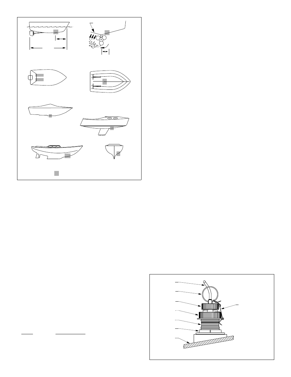
Boat Types
(see Figure 1)
• Displacement hull powerboat—Locate 1/3 of the way along
the LWL and 150–300mm (6–12") off the centerline. The
starboard side of the hull where the propeller blades are moving
downward is preferred.
• Planing hull powerboat—Mount well aft near the centerline and
well inboard of the first set of lifting strakes to ensure that it is in
contact with the water at high speeds. The starboard side of the
hull where the propeller blades are moving downward is preferred.
Outboard and I/O—Mount forward and to the side of the engine(s).
Inboard—Mount well ahead of the propeller(s) and shaft(s).
Stepped hull—Mount just ahead of the first step.
Boats capable of speeds above 25kn (29MPH)—Review
sensor location and operating results of similar boats before
proceeding.
• Fin keel sailboats—Mount to the side of the centerline and
forward of the fin keel 300–600mm (1–2').
• Full keel sailboats—Locate amidships and away from the keel
at the point of minimum deadrise angle.
Installation: B744V, B744VL
Installing the Cap Nut
CAUTION: Avoid cross threading the CAP nut.
Being sure the valve assembly is seated firmly within the housing,
carefully screw the CAP nut in place (see Figure 2). Hand-tighten
only. Do not over tighten.
Installing the Paddlewheel Insert
1. After the sealant cures, inspect the O-rings on the paddlewheel
insert (replace if necessary) and lubricate them with the silicone
lubricant supplied (see Figure 3). The O-rings must be intact and
well lubricated to make a watertight seal.
2. Slide the paddlewheel insert into the housing with the arrow on
the top pointing forward toward the bow. Seat it into place using
a twisting motion until the keys fit into the notches. (The insert
fits one way only.) Be careful not to rotate the outer housing and
disturb the sealant. Screw the INSERT nut in place and hand-
tighten only. Do not over tighten.
3. Attach the safety wire to prevent the insert from backing out in the
unlikely event that the cap nut and/or insert nut fails or is screwed
on incorrectly. Wrap one end of the safety wire tightly around the
stem of the housing and twist it together with the long end (see
Figure 2). Keeping the wire taut throughout, lead the wire straight
up and through one eye in the CAP nut. Thread the wire through
the eye a second time. Lead the wire in a counterclockwise
direction and thread it through the eye in the INSERT nut. Thread
the wire through that eye a second time. Loop the wire through the
pull ring and twist the wire securely to itself.
2
Figure 1.
Best location for the sensor
inboard
pressure waves
1/3
full keel sailboat
displacement hull
(6–12")
fin keel sailboat
150–300mm
LWL
(Load Waterline Length)
stepped hull
outboard and I/O
planing hulls
Copyright © 2005 - 2010 Airmar Technology Corp.
Figure 2. B744V/VL: Cap nut and safety wire
pull ring
hull
safety wire
cap nut
hull nut
stem
cable
Copyright © 2005 - 2013 Airmar Technology Corp.
insert nut
NOTE: Do not remove
the CAP nut to service
the paddlewheel insert.
The valve assembly
will come out.
Aft View