Installation in a cored fiberglass hull – Airmar B744V User Manual
Page 4
4
Bedding the B66V and B66VL
B744V, B744VL—Follow the supplemental
instructions that came with your high-speed fairing.
1. Remove one safety ring, retaining pin, cap nut, and hull nut
from the multisensor. Grasp the paddlewheel insert by the
pull ring and pull slowly upward (see Figure 6).
2. If a fairing is used, thread the multisensor cable through it.
3. Apply a 2mm (1/16") thick layer of marine sealant over the
surface of the multisensor that will contact the fairing (or
hull if no fairing is used) and up the stem, 6mm (1/4")
higher than the combined thickness of the fairing, hull,
backing block, and hull nut. This will seal the hull and to
hold the hull nut securely in place.
4. Slide the fairing (if used) onto the stem and mate the button
with the recess in the multisensor (see Figures 3 and 7).
5. Apply a 2mm (1/16") thick layer of marine sealant to the
side of the fairing that will contact the hull (see Figure 6).
Installing the B66V and B66VL
B744V, B744VL—Follow the supplemental
instructions that came with your high-speed fairing.
Figure 7. Top view
recess
BOW
►
1. From outside the hull, thread the cable through the mounting hole.
2. Push the stem of the multisensor (with the fairing in place) into the
mounting hole using a twisting motion to squeeze out excess
sealant. If an Airmar fairing is used, be sure the button on the fairing
is mated with the recess in the multisensor, the arrow on the fairing
is pointing forward, and the assembly is aligned parallel to the
centerline of the boat (see Figures 3 and 7).
3. From inside the hull, slide the backing block onto the multisensor
cable and stem seating it firmly against the hull. Screw the hull nut in
place and tighten it with slip-joint pliers (see Figure 8).
Wood hull—Allow for the wood to swell.
Caution: Be careful to avoid cross threading the cap nut.
4. Being sure the valve assembly is seated firmly in the housing,
carefully screw the cap nut in place. Hand-tighten only. Do not over
tighten.
5. Remove any excess sealant on the outside of the hull to ensure
smooth water flow over the multisensor.
6. After the sealant cures, inspect and lubricate the O-rings on the
paddlewheel insert with silicone grease or petroleum jelly (see
Figure 9).
7. Slide the paddlewheel insert into the valve assembly with the arrow
on the top pointing forward until it is fully seated. (The insert fits one
way only.) Take care not to rotate the outer housing and disturb the
sealant.
8. Slide the center ring of the safety chain onto the cable. Slide the
retaining pin in place and reattach the safety ring (see Figure 8).
Warning: Always attach the safety wire to prevent the insert from
backing out in the unlikely event that the cap nut fails or is screwed
on incorrectly.
9. Wrap one end of the safety wire tightly around the stem of the
housing and twist it together with the long end. Lead the wire
straight up and through one eye in the cap nut, then through one of
the safety rings. Loop the wire through the pull ring and twist it
securely to itself.
Caution: If the multisensor came with a connector, do not remove it
to ease cable routing. If the cable must be cut and spliced, use
Airmar’s splash-proof Junction Box 33-035 and follow the
instructions provided. Cutting the cable or removing the connector,
except when using Airmar’s junction box, will void the warranty.
10.Route the cable to the instrument, being careful not to tear the
cable jacket when passing it through the bulkhead(s) and other parts
of the boat. To reduce electrical interference, separate the
multisensor cable from other electrical wiring and the engine. Coil
any excess cable and secure it in place using zip-ties to prevent
damage.
11.Refer to the echosounder owner’s manual to connect the
multisensor to the instrument.
Installation in a Cored Fiberglass Hull
The core (wood or foam) must be cut and sealed carefully. The core
must be protected from water seepage, and the hull must be
reinforced to prevent it from crushing under the hull nut allowing the
housing to become loose.
Warning: Always wear safety goggles and a dust mask when drilling.
1. Drill a 3mm or 1/8" pilot hole perpendicular to the waterline from
inside the hull. If there is a rib, strut, or other hull irregularity near the
selected mounting location, drill from the outside (see Figure 10). If
the hole is drilled in the wrong location, drill a second hole in a better
location. Apply masking tape to the outside of the hull over the
incorrect hole and fill it with epoxy.
2. Using the 51mm or 2" hole saw, cut a hole from outside the hull
through the outer skin only.
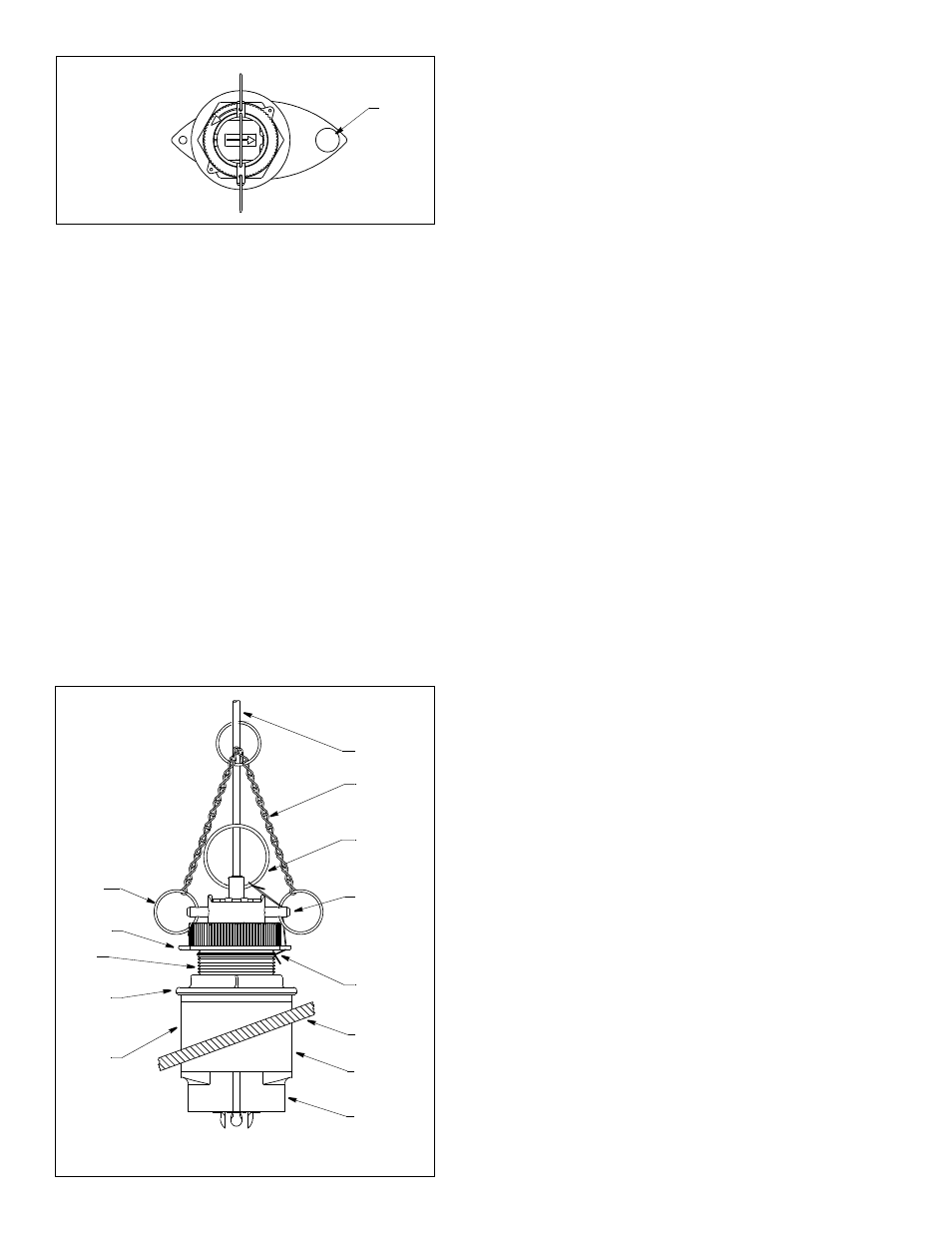
(B744V shown)
Figure 8. Installation (B66V shown)
pull ring
retaining pin
hull
fairing
multisensor
safety chain
safety wire
safety
cap nut
hull nut
backing
stem
cable
block
ring