Antifouling paint, Installation, Hole drilling – Airmar B744V User Manual
Page 3: Cutting the b66v and b66vl fairing
3
Antifouling Paint
Marine growth can accumulate rapidly on the multisensor’s surface
reducing performance in weeks. Surfaces exposed to salt water must
be coated with antifouling paint. Use water-based antifouling paint
only. Never use ketone-based paint since ketones can attack many
plastics possibly damaging the transducer. Reapply paint every 6
months or at the beginning of each boating season.
It is easier to apply antifouling paint before installation, but allow drying
time. Paint the following surfaces (see Figure 4):
• Exposed areas of the housing including the acoustic window
• Bore of the housing up 30mm (1-1/4")
• Outside wall below lower O-ring
• Exposed end of the paddlewheel insert
• Paddlewheel cavity
• Paddlewheel
• Blanking plug below the lower O-ring and the exposed end
Installation
Cored fiberglass hull—Follow separate instructions on page 4.
Caution: Never pull, carry, or hold the multisensor by the cable as this
may sever internal connections.
Hole Drilling
Warning: Always wear safety goggles and a dust mask when drilling.
1. Drill a 3mm or 1/8" pilot hole perpendicular to the waterline from
inside the hull (see Figure 2). If there is a rib, strut, or other hull
irregularity near the selected mounting location, drill from the outside.
If the pilot hole is drilled in the wrong location, drill a second hole in a
better location. Apply masking tape to the outside of the hull over the
incorrect hole and fill it with epoxy.
2. Using the appropriate size hole saw, cut a hole from outside the hull.
Fiberglass or wood hull—Use a 51mm or 2" hole saw.
3. Sand and clean the area around the hole, inside and outside, to
ensure that the sealant will adhere properly to the hull. If there is any
petroleum residue inside the hull, remove it with either mild
household detergent or a weak solvent (alcohol) before sanding.
Cutting the B66V and B66VL Fairing
B744V, B744VL—Follow the supplemental instructions that came with
your high-speed fairing.
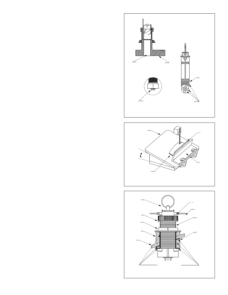
1. Measure the deadrise angle of the hull at the selected location using
a digital level (see Figure 2).
2. Tilt the band saw table to the measured angle and secure the cutting
fence (see Figure 5).
3. Place the fairing on the table, so the cutting guide rests against the
fence. The arrow will point toward you for installation on the port
side and away from you for installation on the starboard side of the
boat.
Caution: The ARROW always points forward toward the bow. Be
sure to orient the fairing on the band saw so the angle cut matches
the intended side of the hull and not the mirror image.
4. The fairing must be between 6–12mm (1/4–1/2") at the narrowest
spot (see Figure 2).
Warning: Always wear safety goggles and a dust mask when drilling.
5. Recheck steps 1 through 4; then cut the fairing.
6. Shape the fairing to the hull as precisely as possible with a rasp or
power tool.
Figure 5. Cutting the fairing (B66V shown)
cutting
guide
band saw
table
deadrise
angle
arrow end
for installation
on port side
fence
Figure 4. Antifouling paint (B744V shown)
Paint outside wall below the lower O-ring
including exposed end, paddlewheel cavity and paddlewheel
Paint exposed housing
lower
O-ring
and bore up 30mm (1-1/4")
paddlewheel
insert
housing
detail
marine sealant
stem
hull nut
backing
hull
fairing
Figure 6. Bedding (B66V shown)
cap nut
retaining pin
safety ring
block
pull ring