Installation – Airmar P79 User Manual
Page 3
Installation
CAUTION: The base must be liquid-tight. To ensure a tight bond,
the hull surface under and around the base must be smooth, free
of paint or any other finish, clean, and dry.
CAUTION: Do not use an epoxy adhesive because it is too brittle.
CAUTION: The top of the transducer must be level when the
installation is complete.
1. Measure the deadrise angle of the hull at the selected location
using an angle finder or digital level (see Figure 4). Measure
carefully, since the installed transducer must be within 5° of
vertical.
2. The hull surface to be bonded must be smooth and free of paint
or any other finish. If the surface is rough, use a disk sander to
smooth an area 100mm (4") in diameter.
3. To ensure a tight bond, clean and dry both the selected area
and the underside of the base. Remove any dust, grease, or oil
with a weak solvent, such as alcohol.
4. Using a carpenter’s square, draw a line on the hull
perpendicular to the keel through the center of the mounting
location. This will be used as a guideline to orient the base.
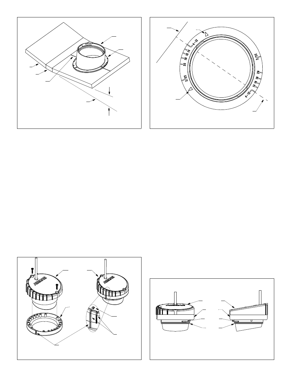
5. The numbers on the flange of the base represent deadrise
angles. Identify the number that most closely corresponds to
the deadrise angle of your hull. Find its match on the opposite
side of the flange. Keeping the keel direction arrows on the side
of the base nearest the keel, align the two raised marks
indicating your deadrise angle with the guideline drawn on the
hull (see Figure 5).
6. When you are satisfied that the location of the transducer is
optimal and the orientation of the base corresponds to the
deadrise angle of your boat, apply a generous bead of silicone
sealant to the underside of the flange of the base. (Follow the
sealant manufacturer’s instructions for its use.) Press the flange
firmly in place to form a liquid-tight seal. Allow the sealant to cure.
7. Slide the transducer into the locking ring (see Figure 6). Turn
the transducer until the rib that most closely corresponds to the
deadrise angle of your hull is aligned with the angle indicator on
the locking ring. To secure the transducer to the locking ring,
insert the two screws. Do not over-tighten the screws.
8. Lubricate the O-ring with petroleum jelly (Vaseline®). This will
help to seal the assembly and prevent the fill-liquid from leaking.
Slide the O-ring onto the transducer assembly (see Figure 7).
3
Figure 4. Deadrise angle and guideline
deadrise
parallel to
hull
waterline
perpendicular
to keel
base
flange
Figure 5. Aligning the flange of the base
keel direction
keel
direction
guideline
keel
arrow
arrow
(4°–12° deadrise angle shown)
Figure 6. Joining the transducer to the locking ring
angle indicator
detail
locking
ring
transducer
ribs
10
•
deadrise
angle
Copyright © 2005 Airmar Technology Corp.
Copyright © 2005 Airmar Technology Corp.
Copyright © 2005 - 2010 Airmar Technology Corp.
guideline
angle
keel
Figure 7. Installing the O-ring and identifying the bosses
O-ring
transducer
front view
side view
locking
ring
NOTE: Lubricate the O-ring with
petroleum jelly before sliding
it onto the transducer assembly.
Copyright © 2005 - 2010 Airmar Technology Corp.
boss (2)