AEC Econo-Cool Chillers User Manual
Page 53
Page 52
AEC Water Temperature Control Units
Figure 8
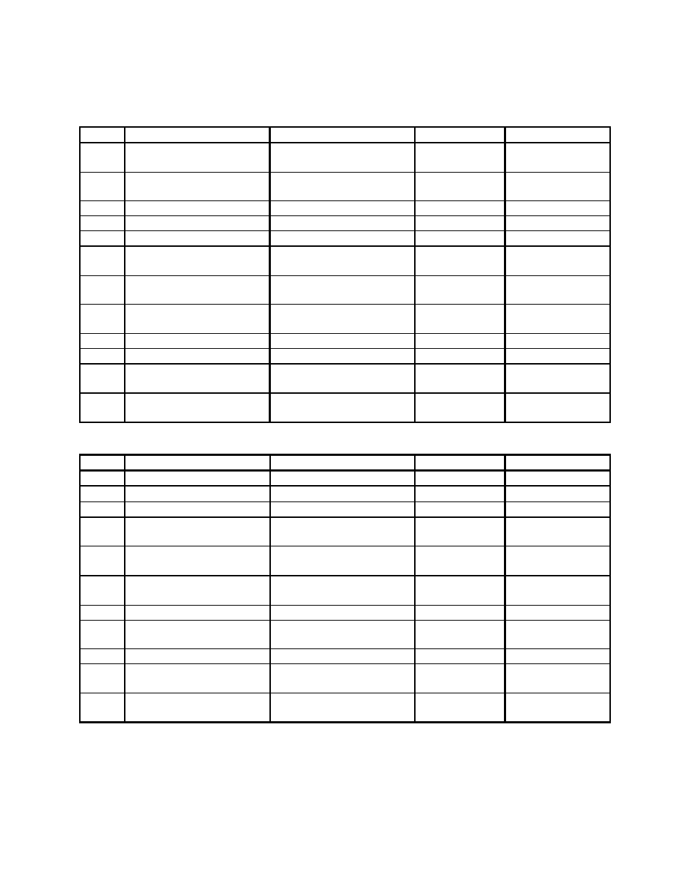
Setting List for Process Temperature Controller (Cont’d.)
Mode
Parameter
Setting range
Default
Solenoid Valve
Level 2 Remote/Local
Only active with comm.
board
Local Default
Level 2
SPrU Sp Ramp Time
Unit
M(Minutes)/
H(Hours)
M Default
Level 2 SPrt Sp Ramp Set Value
0 to 9999 EU
0
Default
Level 2 Mu-5 MV at Stop
-5.0 to 105.0%
0.0
Default
Level 2 Mu-E MV at PV Error
-5.0 to 105.0%
0.0
Default
Level 2 OL-H MV Upper Limit
MV Lower Limit +0.1 to
105%
105.0 Default
Level 2 OL-L MV Lower Limit
-5.0 to MV Upper Limit -
0.1%
-5.0 Default
Level 2
OrL MV Change Rate
Limit
0.0 to 100.0%/SEC
0.0
Default
Level 2 InF Input Digital Filter
0 to 9999 SEC
0
Default
Level 2 ALH2 Alarm 2 Hysteresis
0.01 to 99.99%
0.02
Default
Level 2
In5H Input Shift Upper
Limit
-199.9 to 999.9
°C
0.0 Default
Level 2
In5L Input Shift Lower
Limit
-999.9 to 999.9
°C
0.0 Default
Mode
Parameter
Setting range
Default
Solenoid Valve
Setup In-t Input Type
0 to 21
2
2
Setup d-U
°C/F Selection
°C/F
°C
°F
Setup InIt Parameter Initialize
Yes/No
No
Default
Setup
OUt1 Control Output 1
Assignment
Heat/Cool/Alarm 1/Alarm
2/Alarm 3/ LBA
Heat Default
Setup
OUt2 Control Output 2
Assignment
Heat/Cool/Alarm 1/Alarm
2/Alarm 3/ LBA
Cool Cool
Setup
Sub 1 Auxiliary Output 1
Assignment
Alarm 1/Alm 2/Alm
3/LBA/S.ERR/E333
AL-1 AL-2
Setup Alt1 Alarm 1 Type
0 to 11
2
Default
Setup
AL1n Alarm 1 open in
alarm
NO/NC NO
Default
Setup ALt1 Alarm 2 Type
0 to 11
3
Default
Setup
AL2n Alarm 2 open in
alarm
NO/NC NO
Default
Setup
6rEu Direct/Reverse
Operation
OR-R/OR-D OR-R
Default