ACTi Outdoor Mini PTZ Dome on Dropped Ceiling User Manual
Page 23
Installation Guide
Device
DI
Connection design
TTL - compatible logic levels
Voltage
To trigger (low)
Logic level 0: 0V ~ 0.4V
Normal (high)
Logic level 1: 3.1V ~ 30V
Current
10mA ~ 100mA
DO
Connection design
Transistor (Open Collector)
Voltage & Current
< 24V DC, < 50mA
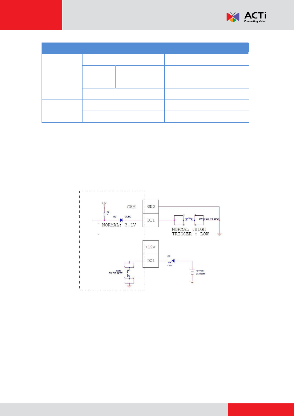
Typical Connection
Based on these specifications, if the DI device has a voltage of 0V ~ 30V or the DO device has a
voltage of < 24V (< 50mA), then the camera can supply internal power to these devices and there
is no need to connect the DI/DO device to an external power source.
In this case, wire connection to Pins 1 to 4. Use the
DIO GND
and
DI
pins to connect a DI device
and use the
DIO PW
and
DO
pins to connect a DO device. See wiring scheme below:
This manual is related to the following products: