ACTi E89 User Manual
Page 30
Hardware Manual
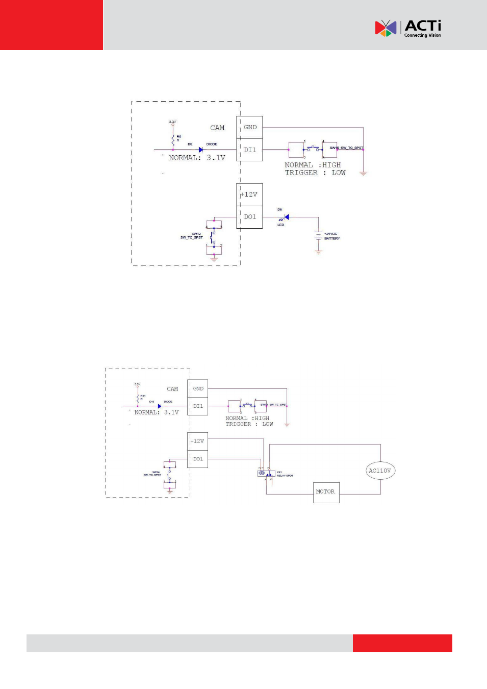
In this case, wire connection to Pins 1 to 4. Use the
GND
and
DI1
pins to connect a DI device and
use the
12V
and
DO1
pins to connect a DO device. See wiring scheme below:
Consequently, to connect a second DI or DO device, wire the connection to Pins 5 to 8.
High Voltage DO Device Connection
Even though the camera provides 12V power, this may not be enough for some high voltage DO
devices, such as a ceiling light or a motor that opens or closes a gate. In this case, there is a
need to connect an external relay. See wiring scheme below:
Note that when choosing an appropriate relay, please refer to its specifications and make sure
they match the above design. The triggering circuit voltage has to be around 12V DC and the
switch-controlled circuit voltage has to match the external power supply (e.g. 110V AC or 220V
AC).
- E815 E816 E817 E822 E610 E616 E617 E618 E621 Outdoor Dome (B8xI8x) on Tilted Wall Outdoor Dome (B8xI8x) on Tilted Wall with Gang Box Converter Outdoor Hemispheric / Fisheye Dome on Tilted Wall with Gang Box Converter Outdoor Hemispheric / Fisheye Dome on Dropped Ceiling with Gang Box Converter Outdoor Hemispheric / Fisheye Dome on Hard Ceiling with Gangbox Converter Outdoor Hemispheric / Fisheye Dome on Straight Wall with Gang Box Converter Outdoor Dome (B8xI8x) on Straight Wall Outdoor Dome (B8xI8x) on Hard Ceiling Outdoor Dome (B8xI8x) on Dropped Ceiling B81 B82 B84 B85 B87 B85 2 Mp Basic WDR Day & Night Outdoor IR Dome PoE Camera with 3x Lens Outdoor Dome (B8xI8x) on Straight Wall with Gang Box Converter Outdoor Dome (B8xI8x) on Dropped Ceiling with Gang Box Converter Outdoor Dome (B8xI8x) on Hard Ceiling with Gang Box Converter