Hardware manual – ACTi E89 User Manual
Page 29
Hardware Manual
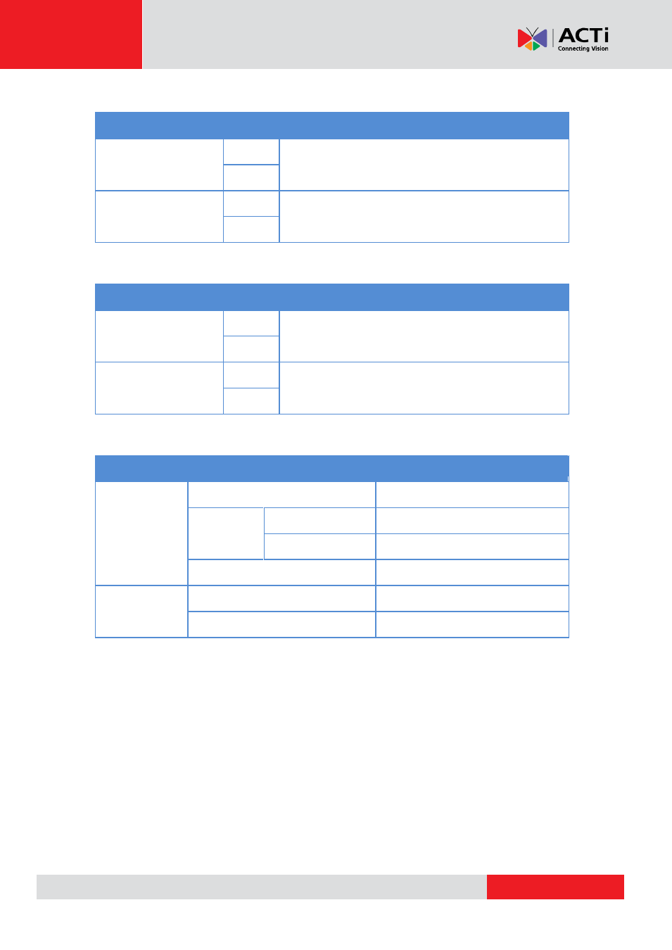
To connect input devices (DI), map the pins to one of the pin combinations below:
Device
Pin
Mapping Instructions
Digital Input 1 (DI1)
GND
Connect the wires of the first input device to
GND
and
DI1
.
DI1
Digital Input 2 (DI2)
GND
Connect the wires of the second input device to
GND
and
DI2
.
DI2
To connect output devices (DO), map the pins to one of the pin combinations below:
Device
Pin
Mapping Instructions
Digital Output 1 (DO1)
12V
Connect the wires of the first output device to
12V
and
DO1
.
DO1
Digital Output 2 (DO2)
12V
Connect the wires of the second output device to
12V
and
DO2
.
DO2
The table below shows the DI/DO connection specifications:
Device
DI
Connection design
TTL - compatible logic levels
Voltage
To trigger (low)
Logic level 0: 0V ~ 0.4V
Normal (high)
Logic level 1: 3.1V ~ 30V
Current
10mA ~ 100mA
DO
Connection design
Transistor (Open Collector)
Voltage & Current
< 24V DC, < 50mA
Typical Connection
Based on these specifications, if the DI device has a voltage of 0V ~ 30V or the DO device has a
voltage of < 24V (< 50mA), then the camera can supply internal power to these devices and there
is no need to connect the DI/DO device to an external power source.
- E815 E816 E817 E822 E610 E616 E617 E618 E621 Outdoor Dome (B8xI8x) on Tilted Wall Outdoor Dome (B8xI8x) on Tilted Wall with Gang Box Converter Outdoor Hemispheric / Fisheye Dome on Tilted Wall with Gang Box Converter Outdoor Hemispheric / Fisheye Dome on Dropped Ceiling with Gang Box Converter Outdoor Hemispheric / Fisheye Dome on Hard Ceiling with Gangbox Converter Outdoor Hemispheric / Fisheye Dome on Straight Wall with Gang Box Converter Outdoor Dome (B8xI8x) on Straight Wall Outdoor Dome (B8xI8x) on Hard Ceiling Outdoor Dome (B8xI8x) on Dropped Ceiling B81 B82 B84 B85 B87 B85 2 Mp Basic WDR Day & Night Outdoor IR Dome PoE Camera with 3x Lens Outdoor Dome (B8xI8x) on Straight Wall with Gang Box Converter Outdoor Dome (B8xI8x) on Dropped Ceiling with Gang Box Converter Outdoor Dome (B8xI8x) on Hard Ceiling with Gang Box Converter