Westermo RM-505U-K User Manual
Page 29
man_505U-K_1.4.doc
Dec 2008
ELPRO Technologies Pty Ltd 2008
Page 29
1
-
-
Not Used.
2
RD
Out
Receive Data - Serial Data Output (High = 0, Low = 1)
3
TD
In
Transmit Data - Serial Data Input (High = 0, Low = 1)
4
DTR
In
Data Terminal Ready - used by 505K as a "wake-up" signal
5
SG
-
Signal Ground
6
-
-
Not Used.
7
-
-
Not Used.
8
-
-
Not Used.
9
-
-
Not Used.
The DTR signal must be connected to the 505K to enable communications and “wake up” the
microprocessor. This means that the DTR wire must be connected - the PC does not need to
control DTR. When communications is established, the green LED will light continuously.
The serial port communicates at a baud rate of 9600 baud, 8 bits, no parity, one stop bit.
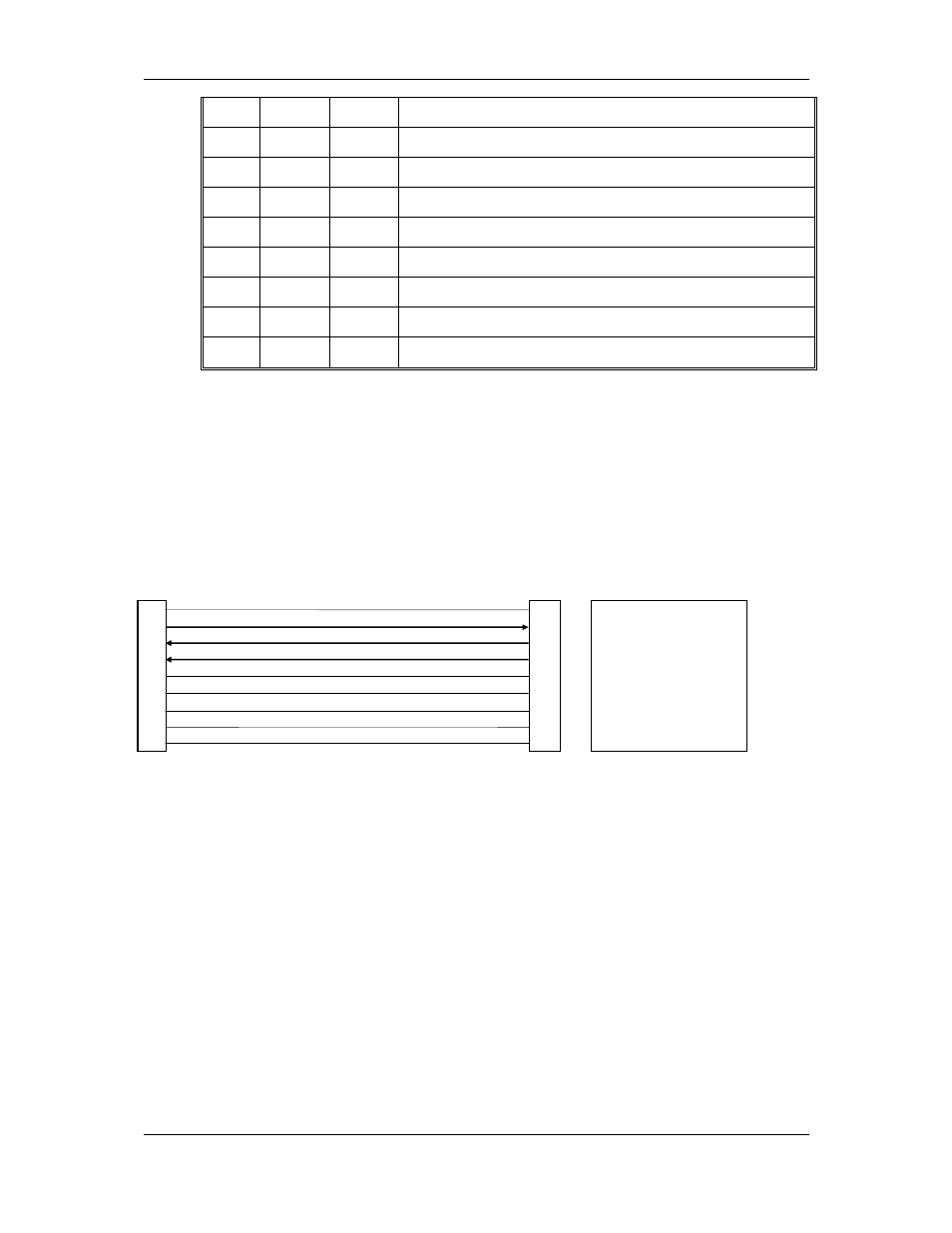
An example cable drawing for connection to a personal computer is detailed below:
E505 DB9 (M) Connector
Computer DB9 (F) Connector
1
1
Not Used - optional
2
2
Receive Data
3
3
Transmit Data
4
4
DTR
5
5
Signal Ground
6
6
Not Used - optional
7
7
Not Used - optional
8
8
Not Used - optional
9
9
Not Used - optional