Outside air humidity sensor – WattMaster MG331-21-VAVCAV User Manual
Page 38
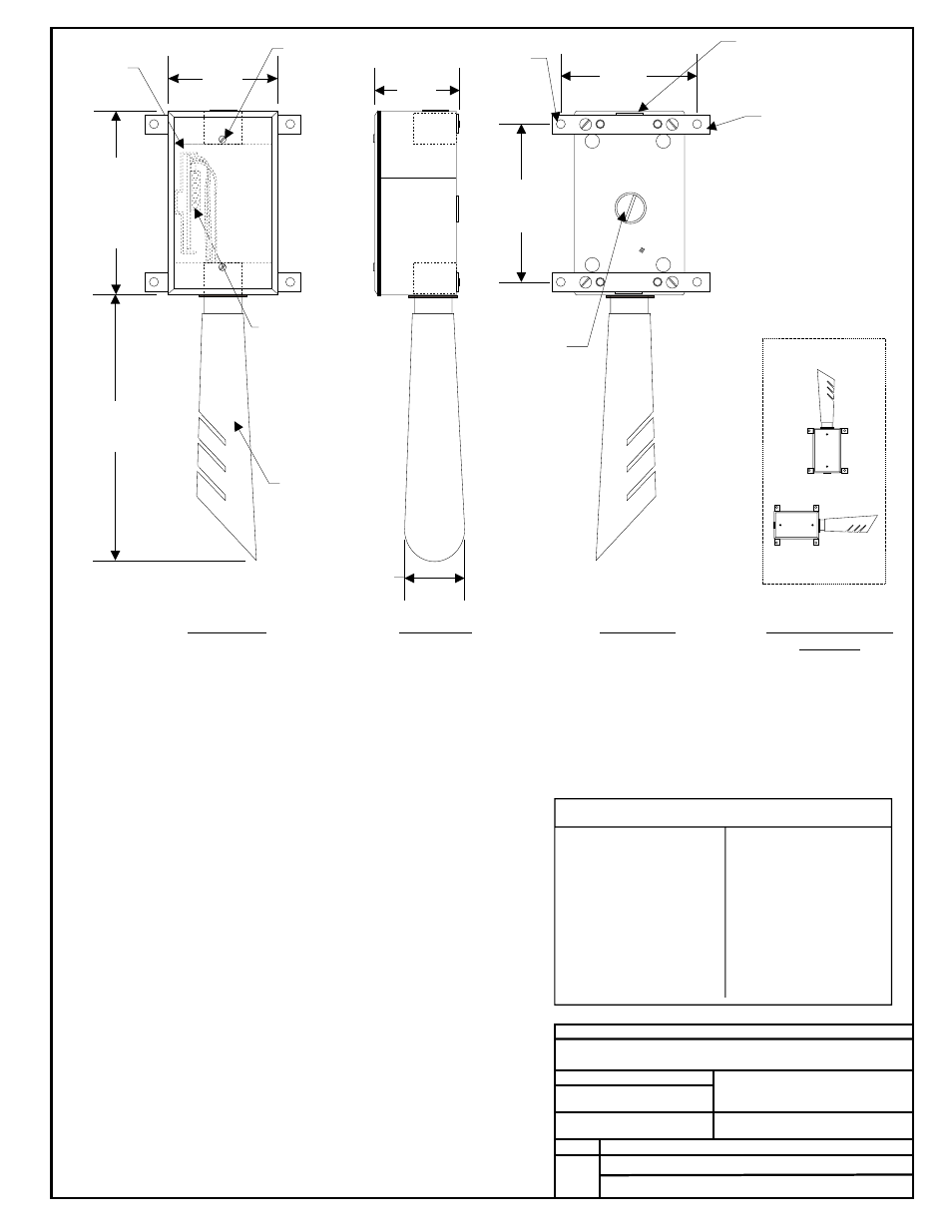
1.63"
Notes:
FILENAME
DATE:
B. CREWS
DESCRIPTION:
PAGE
DRAWN BY:
Outside Air Humidity Sensor
1
JOB NAME
4.)All Wiring To Be In Accordance With
Local And National Electrical Codes
And Specifications.
3.)Gasket Must Be Installed Under Cover
Plate To Provide Raintight Seal.
Rainwater Will Damage Sensor!
05/14/01
G-OA-HUMID1.CDR
OE265-03
Front View
Side View
Back View
Humidity Sensor Current/Voltage Chart
RH
Output*
Output
mA
VDC*
0...............4.00...........1.00
5...............4.80...........1.20
10..............5.60...........1.40
15..............6.40...........1.60
20..............7.20...........1.80
25..............8.00...........2.00
30..............8.80...........2.20
35..............9.60...........2.40
40..............10.40.........2.60
45..............11.20 .........2.80
50..............12.00.........3.00
%
RH
Output*
Output
%
mA
VDC*
55..............12.80.........3.20
60..............13.60.........3.40
65..............14.40.........3.60
70..............15.20.........3.80
75..............16.00.........4.00
80..............16.80.........4.20
85..............17.60.........4.40
90..............18.40.........4.60
95..............19.20.........4.80
100............20.00.........5.00
4.63“
Closure Plug
CAUTION!
See Note 2
Closure Plug
CAUTION!
See Note 2
Gasketed Cover
CAUTION!
See Note 3
2.)Unused Conduit Opening(s) Must
Have Closure Plugs Installed And Must
Be Coated with Sealing Compound To
Provide Raintight Seal. Rainwater Will
Damage Sensor!
1.)The Outside Air Sensor Must Be
Mounted In A Horizontal Position As
Shown (Sensor Tube Pointing Left
or Right with Slots Pointing Down).
Sensor Must
Be Located Where It Will Not Be
Affected By Direct Sunlight Or Heat
Producing Equipment. If Possible
Mount Under Roof Eave Or Similar
Protected Location. If Sensor Is Not
Located As Specified, Erroneous
Outside Air Humidity Readings Will
Result.
Water Must Not Be Allowed To
Stand In Sensor Tube. Rainwater
Will Damage Sensor.
0.19 Dia.
Hole Typ.
Cover
Mounting
Screw
Wiring Terminal.
Connect Wiring
To Controller Using
24 Gauge Minimum
Wire. Only 2
Conductors are
Required.
-
Typ.
Sensor Tube
CAUTION!
See Note 1
Outside Air Relative Humidity Sensor OE265-03
Mounting Bar
& Screws - Typ.
*Chart Notes:
1. Be sure that +24VDC power is being supplied to the sensor. For voltage measurement s
onnect the meter between ground and the input terminal on the controller
board that is connected to the sensor. The input on the controller board must have a 250 ohm
resistor to ground installed and have it’s associated pull-up resistor removed for the sensor to
function properly. For current measurement set the ammeter to DC Amps and connect the
meter’s lead in series with the T1 terminal on the sensor. Use an accurate humidity
measurement device to determine RH (relative humidity) such as an aspirating psychrometer.
Use the Output VDC column to read the Output Voltage or the Output mA column to read the
Output Amperage corresponding with the RH percentage measured with the psychrometer. If the
measured voltage or amperage is within 3% of what is listed for the corresponding RH, then the
sensor is functioning properly.
et the
meter to DC Volts. C
1/2
Correct
Incorrect
See Note #1
Sensor Mounting
Postion
2.88“
6.00
3.50“
3.19“
2.25“